Jeep Parts Wiki | Ford Parts Wiki
Home | Search | Browse
Prev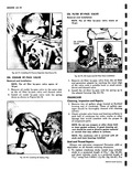
 Next
Next
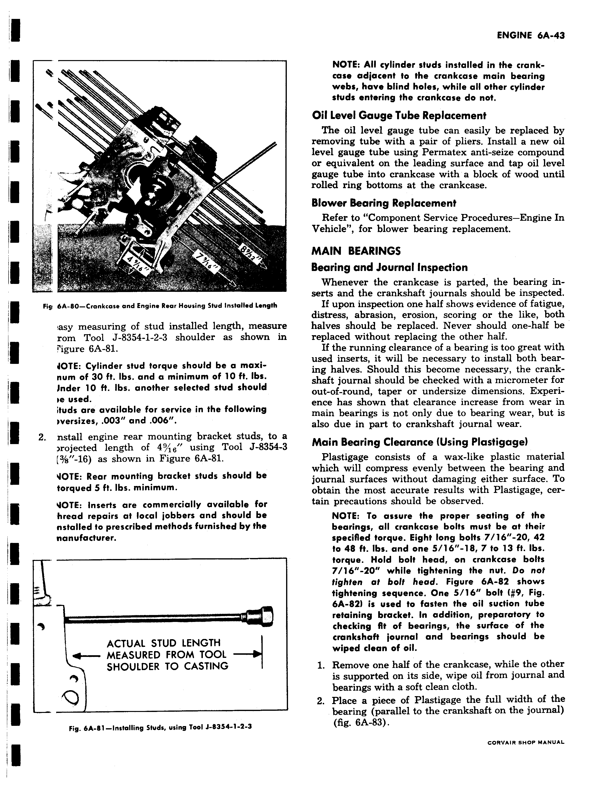
i i J Y r i Fig 6A 80 Crankcase and Engine Rear Housing Stud Installed Length asy measuring of stud installed length measure rom Tool J 8354 1 2 3 shoulder as shown in i rigure 6A 81 JOTE Cylinder stud torque should be a maxinum of 30 ft Ibs and a minimum of 10 ft Ibs i Jnder 10 ft Ibs another selected stud should oe used ituds are available for service in the following i versizes 003 and OOb 2 nstall engine rear mounting bracket studs to a rojected length of 4 16 using Tool J 8354 3 3 s 16 as shown in Figure 6A 81 i VOTE Rear mounting bracket studs should be torqued 5 ft Ibs minimum i VOTE Inserts are commercially available for hread repairs at local jobbers and should be nstalled to prescribed methods furnished by the nanufacturer rrrrrrrr ACTUAL STUD LENGTH f MEASURED FROM TOOL SHOULDER TO CASTING Fig 6A 81 Installing Studs using Tool J 8354 1 2 3 NOTE All cylinder studs installed in the crankcase adjacent to the crankcase main bearing webs have blind holes while all other cylinder studs entering the crankcase do not Oil Level Gauge Tube Replacement The oil level gauge tube can easily be replaced by removing tube with a pair of pliers Install a new oil level gauge tube using Permatex anti seize compound or equivalent on the leading surface and tap oil level gauge tube into crankcase with a block of wood until rolled ring bottoms at the crankcase Blower Bearing Replacement Refer to Component Service Procedures Engine In Vehicle for blower bearing replacement MAIN BEARINGS Bearing and Journal Inspection Whenever the crankcase is parted the bearing inserts and the crankshaft journals should be inspected If upon inspection one half shows evidence of fatigue distress abrasion erosion scoring or the like both halves should be replaced Never should one half be replaced without replacing the other half If the running clearance of a bearing is too great with used inserts it will be necessary to install both bearing halves Should this become necessary the crankshaft journal should be checked with a micrometer for out of round taper or undersize dimensions Experience has shown that clearance increase from wear in main bearings is not only due to bearing wear but is also due in part to crankshaft journal wear Main Bearing Clearance Using Plastigage Plastigage consists of a wax like plastic material which will compress evenly between the bearing and journal surfaces without damaging either surface To obtain the most accurate results with Plastigage certain precautions should be observed NOTE To assure the proper seating of the bearings all crankcase bolts must be at their specified torque Eight long bolts 7 16 20 42 to 48 ft Ibs and one 5 16 18 7 to 13 ft Ibs torque Hold bolt head on crankcase bolts 7 16 20 while tightening the nut Do not tighten at bolt head Figure 6A 82 shows tightening sequence One 5 16 bolt 9 Fig 6A 82 is used to fasten the oil suction tube retaining bracket In addition preparatory to checking Rt of bearings the surface of the crankshaft journal and bearings should be wiped dean of oil 1 Remove one half of the crankcase while the other is supported on its side wipe oil from journal and bearings with a soft clean cloth 2 Place a piece of Plastigage the full width of the bearing parallel to the crankshaft on the journal fig 6A 83 GORVAIR SHOP MANUAL