Jeep Parts Wiki | Ford Parts Wiki
Home | Search | Browse | Marketplace | Messages | FAQ | Guest
Prev

 Next
Next
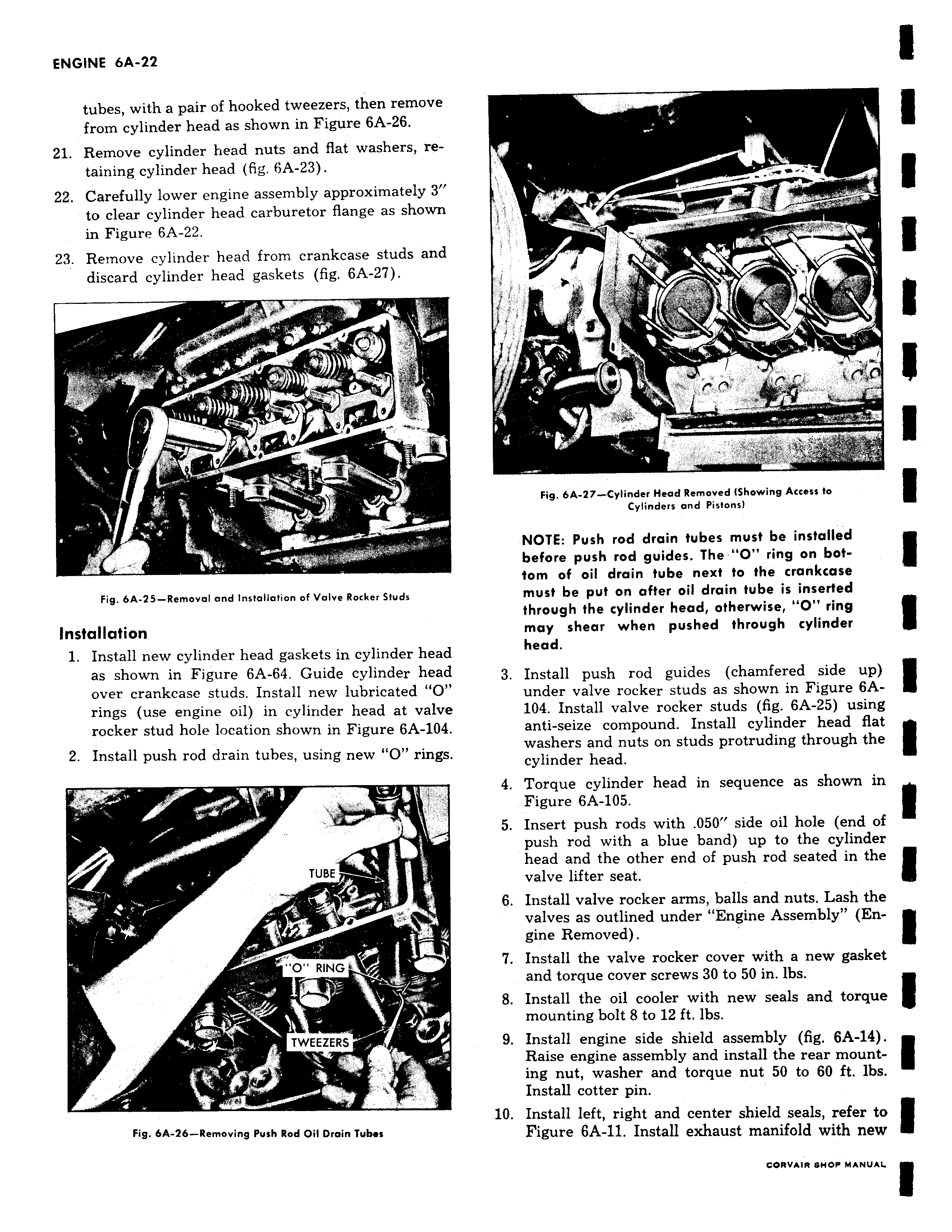
r r v k r v w 41 y l 8 Fig 6A 27 Cylinder Head Removed IShowing Access to Cylinders and Pistons NOTE Push rod drain tubes must be installed before push rod guides The O ring on bottom of oil drain tube next to the crankcase must be put on after oil drain tube is inserted through the cylinder head otherwise O ring may shear when pushed through cylinder head 3 Install push rod guides chamfered side up under valve rocker studs as shown in Figure 6A104 Install valve rocker studs fig 6A 25 using anti seize compound Install cylinder head flat washers and nuts on studs protruding through the cylinder head 4 Torque cylinder head in sequence as shown in Figure 6A 105 5 Insert push rods with 050 side oil hole end of push rod with a blue band up to the cylinder head and the other end of push rod seated in the valve lifter seat 6 Install valve rocker arms balls and nuts Lash the valves as outlined under Engine Assembly Engine Removed 7 Install the valve rocker cover with a new gasket and torque cover screws 30 to 50 in ibs 8 Install the oil cooler with new seals and torque mounting bolt 8 to 12 ft lbs 9 Install engine side shield assembly fig 6A 14 Raise engine assembly and install the rear mounting nut washer and torque nut 50 to 60 ft lbs Install cotter pin 10 Install left right and center shield seals refer to Figure 6A 11 Install exhaust manifold with new

 Next
Next