Jeep Parts Wiki | Ford Parts Wiki
Home | Search | Browse | Marketplace | Messages | FAQ | Guest
Prev

 Next
Next
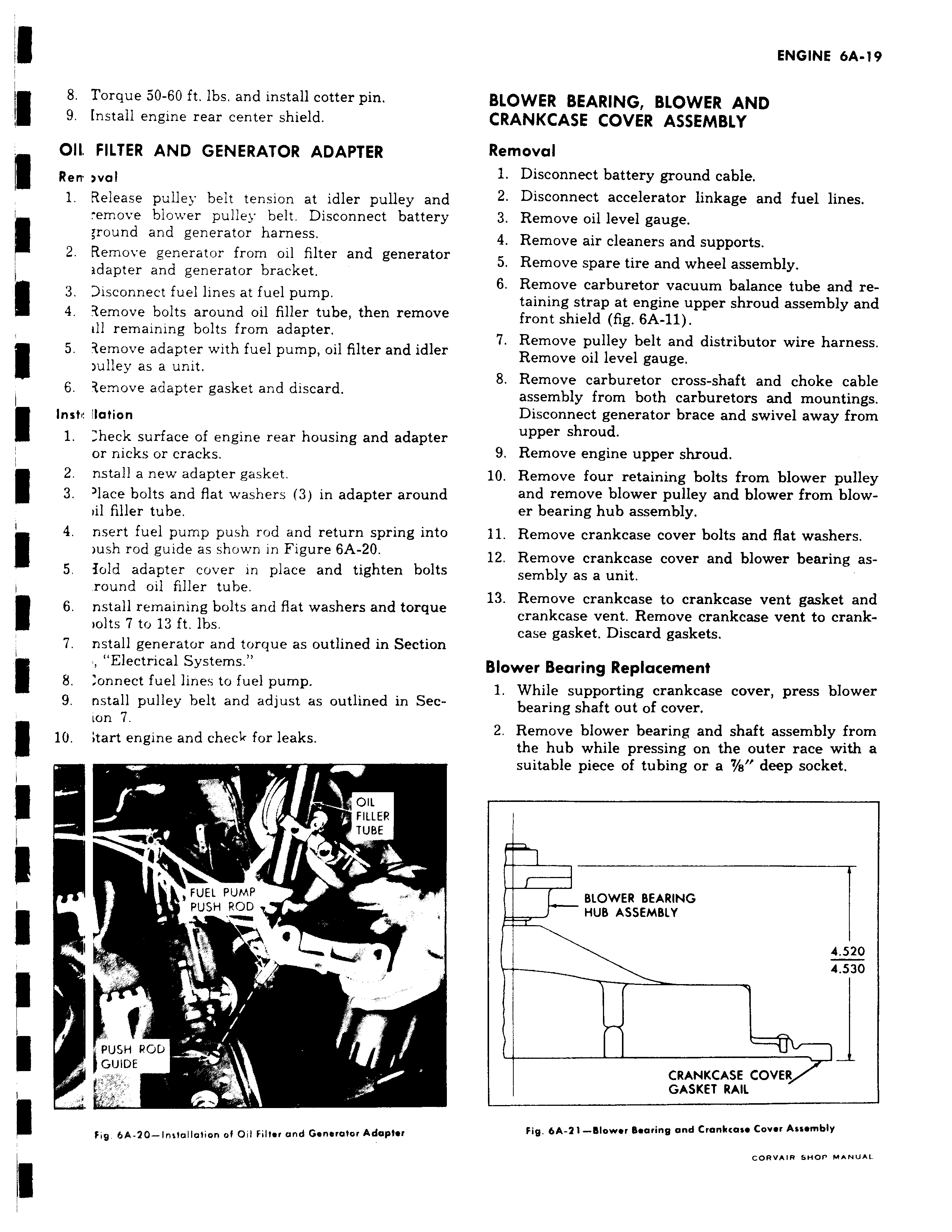
8 Torque 50 60 ft lbs and install cotter pin 9 Install engine rear center shield OII FILTER AND GENERATOR ADAPTER Rerr wal 1 Release pulley belt tension at idler pulley and emove blower pulley belt Disconnect battery e round and generator harness 2 Remove generator from oil filter and generator adapter and generator bracket 3 Disconnect fuel lines at fuel pump 4 3emove bolts around oil filler tube then remove ill remaining bolts from adapter 5 iemove adapter with fuel pump oil filter and idler ulley as a unit 6 3emove adapter gasket and discard I Inste Ilation 1 heck surface of engine rear housing and adapter or nicks or cracks 2 nstall a new adapter gasket 3 lace bolts and flat washers 3 in adapter around dl filler tube 4 nsert fuel pump push rod and return spring into ush rod guide as shown in Figure 6A 20 5 fold adapter cover in place and tighten bolts round oil filler tube 6 nstall remaining bolts and flat washers and torque tolts 7 to 13 ft Ibs 7 nstall generator and torque as outlined in Section Electrical Systems 8 onnect fuel lines to fuel pump 9 nstall pulley belt and adjust as outlined in Secion 7 lU tart engine and check for leaks OIL FILLER TUBE y FUEL PUMP r PUSH ROD J PUSH POD GUIDE k Fig 6A 20 Intlallalion of Oil Filter and Generator Adaptor BLOWER BEARING BLOWER AND CRANKCASE COVER ASSEMBLY Removal 1 Disconnect battery ground cable 2 Disconnect accelerator linkage and fuel lines 3 Remove oil level gauge 4 Remove air cleaners and supports 5 Remove spare tire and wheel assembly 6 Remove carburetor vacuum balance tube and retaining strap at engine upper shroud assembly and front shield fig 6A 11 7 Remove pulley belt and distributor wire harness Remove oil level gauge 8 Remove carburetor cross shaft and choke cable assembly from both carburetors and mountings Disconnect generator brace and swivel away from upper shroud 9 Remove engine upper shroud 10 Remove four retaining bolts from blower pulley and remove blower pulley and blower from blower bearing hub assembly 11 Remove crankcase cover bolts and flat washers 12 Remove crankcase cover and blower bearing assembly as a unit 13 Remove crankcase to crankcase vent gasket and crankcase vent Remove crankcase vent to crankcase gasket Discard gaskets Blower Bearing Replacement 1 While supporting crankcase cover press blower bearing shaft out of cover 2 Remove blower bearing and shaft assembly from the hub while pressing on the outer race with a suitable piece of tubing or a 7 e deep socket BLOWER BEARING HUB ASSEMBLY 4 520 4 530 CRANKCASE COVER GASKET RAIL Fig 6A 21 plower Bearing and Crankcase Cover Assembly CORVAIR SHOP MANUAL

 Next
Next