Jeep Parts Wiki | Ford Parts Wiki
Home | Search | Browse
Prev

 Next
Next
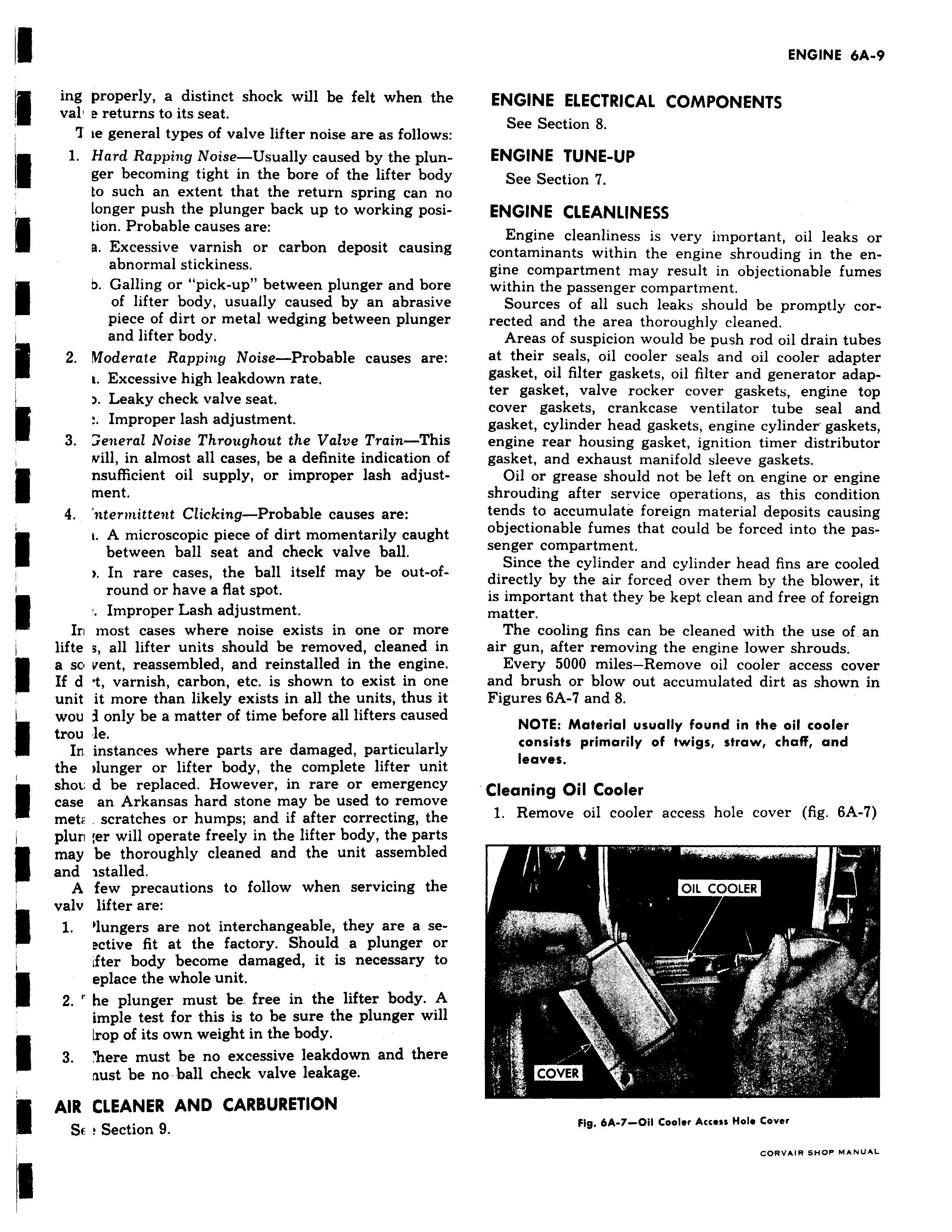
ing properly a distinct shock will be felt when the val e returns to its seat T ie general types of valve lifter noise are as follows 1 Hard Rapping Noise Usually caused by the plunger becoming tight in the bore of the lifter body to such an extent that the return spring can no longer push the plunger back up to working position Probable causes are a Excessive varnish or carbon deposit causing abnormal stickiness b Galling or pick up between plunger and bore of lifter body usually caused by an abrasive piece of dirt or metal wedging between plunger and lifter body 2 Nloderate Rapping Noise Probable causes are t Excessive high leakdown rate Leaky check valve seat Improper lash adjustment 3 aeneral Noise Throughout the Valve Train This will in almost all cases be a definite indication of nsufficient oil supply or improper lash adjust ment 4 nternnittent Clicking Probable causes are i A microscopic piece of dirt momentarily caught between ball seat and check valve ball In rare cases the ball itself may be out ofround or have a flat spot Improper Lash adjustment Irl most cases where noise exists in one or more lifte s all lifter units should be removed cleaned in a sc vent reassembled and reinstalled in the engine If d t varnish carbon etc is shown to exist in one unit it more than likely exists in all the units thus it wou i only be a matter of time before all lifters caused trou 1e In instances where parts are damaged particularly the r lunger or lifter body the complete lifter unit shot d be replaced However in rare or emergency case an Arkansas hard stone may be used to remove metr scratches or humps and if after correcting the plun er will operate freely in the lifter body the parts may be thoroughly cleaned and the unit assembled and istalled A few precautions to follow when servicing the valv lifter are 1 Olungers are not interchangeable they are a seective fit at the factory Should a plunger or ifter body become damaged it is necessary to eplace the whole unit 2 he plunger must be free in the lifter body A imple test for this is to be sure the plunger will Irop of its own weight in the body 3 here must be no excessive leakdown and there nust be no ball check valve leakage AIR CLEANER AND CARBURETION Se r Section 9 ENGINE ELECTRICAL COMPONENTS See Section 8 ENGINE TUNE UP See Section 7 ENGINE CLEANLINESS Engine cleanliness is very important oil leaks or contaminants within the engine shrouding in the engine compartment may result in objectionable fumes within the passenger compartment Sources of all such leaks should be promptly corrected and the area thoroughly cleaned Areas of suspicion would be push rod oil drain tubes at their seals oil cooler seals and oil cooler adapter gasket oil filter gaskets oil filter and generator adapter gasket valve rocker cover gaskets engine top cover gaskets crankcase ventilator tube seal and gasket cylinder head gaskets engine cylinder gaskets engine rear housing gasket ignition timer distributor gasket and exhaust manifold sleeve gaskets Oil or grease should not be left on engine or engine shrouding after service operations as this condition tends to accumulate foreign material deposits causing objectionable fumes that could be forced into the passenger compartment Since the cylinder and cylinder head fins are cooled directly by the air forced over them by the blower it is important that they be kept clean and free of foreign matter The cooling fins can be cleaned with the use of an air gun after removing the engine lower shrouds Every 5000 miles Remove oil cooler access cover and brush or blow out accumulated dirt as shown in Figures 6A 7 and 8 NOTE Material usually found in the oil cooler consists primarily of twigs straw chaff and leaves Cleaning Oil Cooler 1 Remove oil cooler access hole cover fig 6A 7 OIL COOLER Ilr COVER Fig 6A 7 Oil Cooler Access Hole Cover CORVAIR SHOP MANUAL

 Next
Next