Jeep Parts Wiki | Ford Parts Wiki
Home | Search | Browse
Prev
 Next
Next
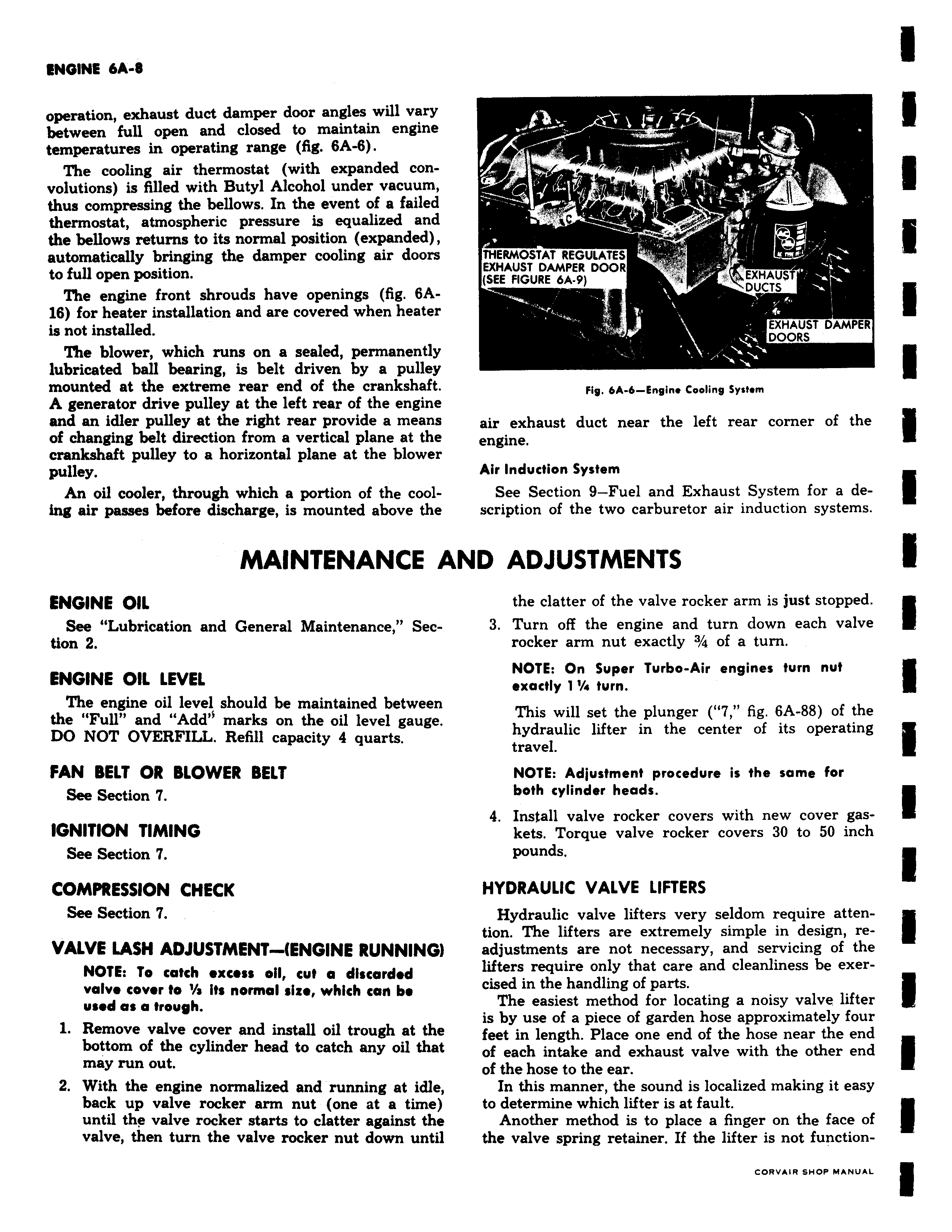
CINVInc vM v operation exhaust duct damper door angles will vary between full open and closed to maintain engine temperatures in operating range fig 6A 6 The cooling air thermostat with expanded convolutions is filled with Butyl Alcohol under vacuum thus compressing the bellows In the event of a failed thermostat atmospheric pressure is equalized and the bellows returns to its normal position expanded automatically bringing the damper cooling air doors to full open position The engine front shrouds have openings fig 6A16 for heater installation and are covered when heater is not installed The blower which runs on a sealed permanently lubricated ball bearing is belt driven by a pulley mounted at the extreme rear end of the crankshaft A generator drive pulley at the left rear of the engine and an idler pulley at the right rear provide a means of changing belt direction from a vertical plane at the crankshaft pulley to a horizontal plane at the blower pulley An oil cooler through which a portion of the cooling air passes before discharge is mounted above the MAINTENANCE A ENGINE OIL See Lubrication and General Maintenance Section 2 ENGINE OIL LEVEL The engine oil level should be maintained between the Full and Add marks on the oil level gauge DO NOT OVERFILL Refill capacity 4 quarts FAN BELT OR BLOWER BELT See Section IGNITION TIMING See Section 7 COMPRESSION CHECK See Section 7 VALVE LASH ADJUSTMENT ENGINE RUNNING NOTE To catch excess oil cut a discarded valve cover to a Its normal size which can be used as a trough 1 Remove valve cover and install oil trough at the bottom of the cylinder head to catch any oil that may run out 2 With the engine normalized and running at idle back up valve rocker arm nut one at a time until the valve rocker starts to clatter against the valve then turn the valve rocker nut down until R i C THERMOSTAT REGULATES EXHAUST DAMPER DOOR SEE FIGURE 6A 9 EXHAU T DUCTS EXHAUST DAMPER DOORS Fig 6A 6 Engin Cooling System air exhaust duct near the left rear corner of the engine Air Induction System See Section 9 Fuel and Exhaust System for a description of the two carburetor air induction systems ND ADJUSTMENTS the clatter of the valve rocker arm is just stopped 3 Turn off the engine and turn down each valve rocker arm nut exactly 3 4 of a turn NOTE On Super Turbo Air engines turn nut exactly 1 turn This will set the plunger 7 fig 6A 88 of the hydraulic lifter in the center of its operating travel NOTE Adjustment procedure is the same for both cylinder heads 4 Install valve rocker covers with new cover gaskets Torque valve rocker covers 30 to 50 inch pounds HYDRAULIC VALVE LIFTERS Hydraulic valve lifters very seldom require attention The lifters are extremely simple in design readjustments are not necessary and servicing of the lifters require only that care and cleanliness be exercised in the handling of parts The easiest method for locating a noisy valve lifter is by use of a piece of garden hose approximately four feet in length Place one end of the hose near the end of each intake and exhaust valve with the other end of the hose to the ear In this manner the sound is localized making it easy to determine which lifter is at fault Another method is to place a finger on the face of the valve spring retainer If the lifter is not function