Jeep Parts Wiki | Ford Parts Wiki
Home | Search | Browse
Prev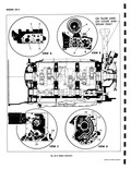
 Next
Next
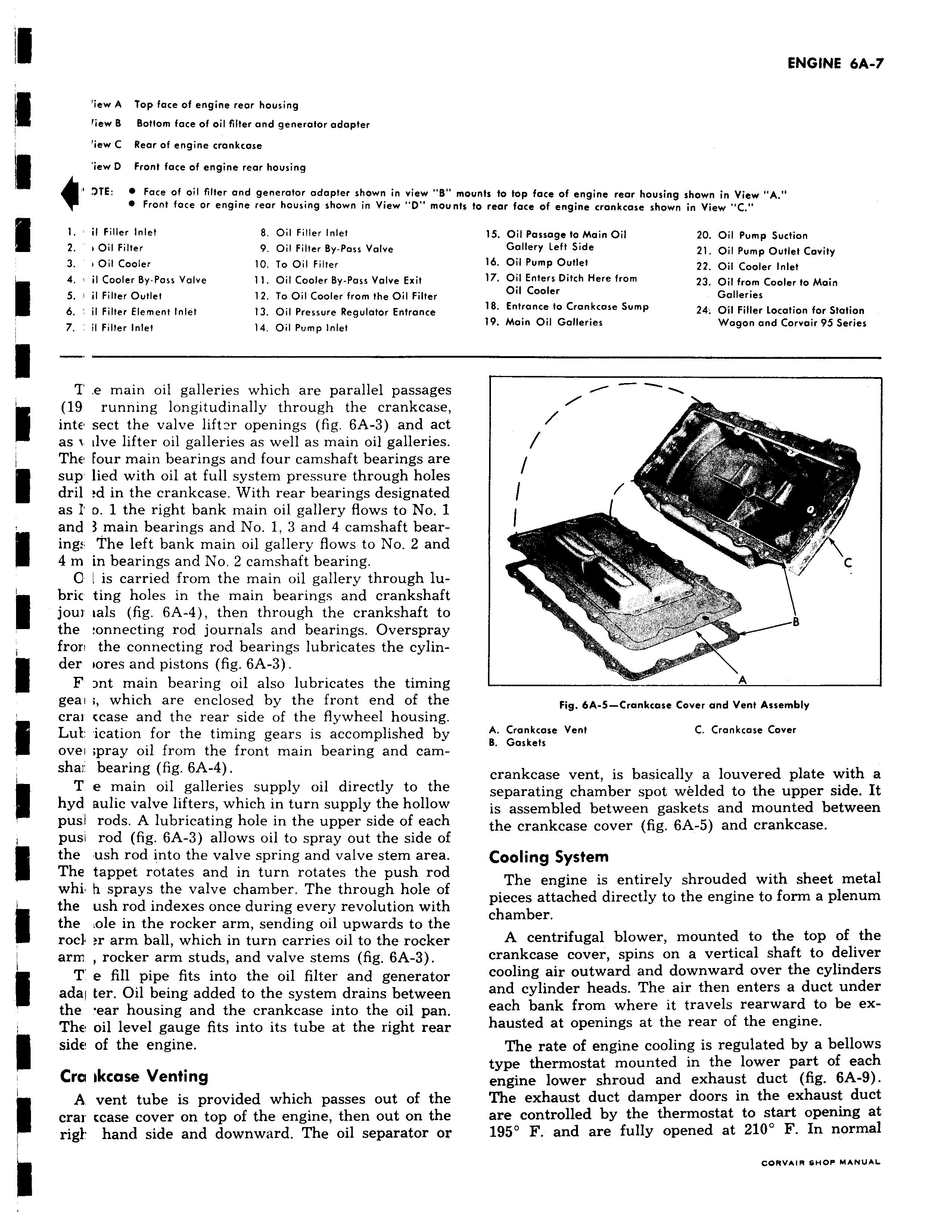
iew A Top face of engine rear housing tiew B Bottom face of oil filter and generator adapter iew C Rear of engine crankcase iew D Front face of engine rear housing NE 0 Face of oil filter and generator adapter shown in view B Front face or engine rear housing shown in View D mou l il Filler Inlet 8 Oil Filler Inlet 2 v Oil Filter 9 Oil Filler By Pass Valve 3 v Oil Cooler 10 To Oil Filter 4 il Cooler By Pass Valve 11 Oil Cooler By Pass Valve Exit 5 i il Filter Outlet 12 To Oil Cooler from the Oil Filter 6 il Filter Element Inlet 13 Oil Pressure Regulator Entrance 7 il Filler Inlet 14 Oil Pump Inlet T e main oil galleries which are parallel passages 19 running longitudinally through the crankcase inte sect the valve lift2r openings fig 6A 3 and act as i tlve lifter oil galleries as well as main oil galleries The four main bearings and four camshaft bearings are sup lied with oil at full system pressure through holes dril d in the crankcase With rear bearings designated as I D 1 the right bank main oil gallery flows to No 1 and 3 main bearings and No 1 3 and 4 camshaft bearing The left bank main oil gallery flows to No 2 and 4 m in bearings and No 2 camshaft bearing 0 I is carried from the main oil gallery through lu bric ting holes in the main bearings and crankshaft f jour fals fig 6A 4 then through the crankshaft to the onnecting rod journals and bearings Overspray fron the connecting rod bearings lubricates the cylinder tores and pistons fig 6A 3 F nt main bearing oil also lubricates the timing geai which are enclosed by the front end of the cral case and the rear side of the flywheel housing Luk ication for the timing gears is accomplished by ovei pray oil from the front main bearing and camshar bearing fig 6A 4 T e main oil galleries supply oil directly to the hyd aulic valve lifters which in turn supply the hollow pus rods A lubricating hole in the upper side of each pusi rod fig 6A 3 allows oil to spray out the side of the ush rod into the valve spring and valve stem area The tappet rotates and in turn rotates the push rod whi h sprays the valve chamber The through hole of the ush rod indexes once during every revolution with the ole in the rocker arm sending oil upwards to the rocl ar arm ball which in turn carries oil to the rocker arm rocker arm studs and valve stems fig 6A 3 T e fill pipe fits into the oil filter and generator adal ter Oil being added to the system drains between the ear housing and the crankcase into the oil pan The oil level gauge fits into its tube at the right rear side of the engine Cra rlkcase Venting A vent tube is provided which passes out of the crar icase cover on top of the engine then out on the righ hand side and downward The oil separator or mounts to fop face of engine rear housing shown in View A its to rear face of engine crankcase shown in View C 15 Oil Passage to Main Oil 20 Oil Pump Suction Gallery Left Side 21 Oil Pump Outlet Cavity 16 Oil Pump Outlet 22 Oil Cooler Inlet 17 Oil Enters Ditch Here from 23 Oil from Cooler to Main Oil Cooler Galleries 18 Entrance to Crankcase Sump 24 Oil Filler Location for Station 19 Main Oil Galleries Wagon and Corvair 95 Series C 1 Fig 6A 5 Crankcase Cover and Vent Assembly A Crankcase Vent C Crankcase Cover B Gaskets crankcase vent is basically a louvered plate with a separating chamber spot welded to the upper side It is assembled between gaskets and mounted between the crankcase cover fig 6A 5 and crankcase Cooling System The engine is entirely shrouded with sheet metal pieces attached directly to the engine to form a plenum chamber A centrifugal blower mounted to the top of the crankcase cover spins on a vertical shaft to deliver cooling air outward and downward over the cylinders and cylinder heads The air then enters a duct under each bank from where it travels rearward to be exhausted at openings at the rear of the engine The rate of engine cooling is regulated by a bellows type thermostat mounted in the lower part of each engine lower shroud and exhaust duct fig 6A 9 The exhaust duct damper doors in the exhaust duct are controlled by the thermostat to start opening at 195 F and are fully opened at 210 F In normal