Jeep Parts Wiki | Ford Parts Wiki
Home | Search | Browse
Prev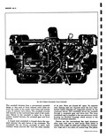
 Next
Next
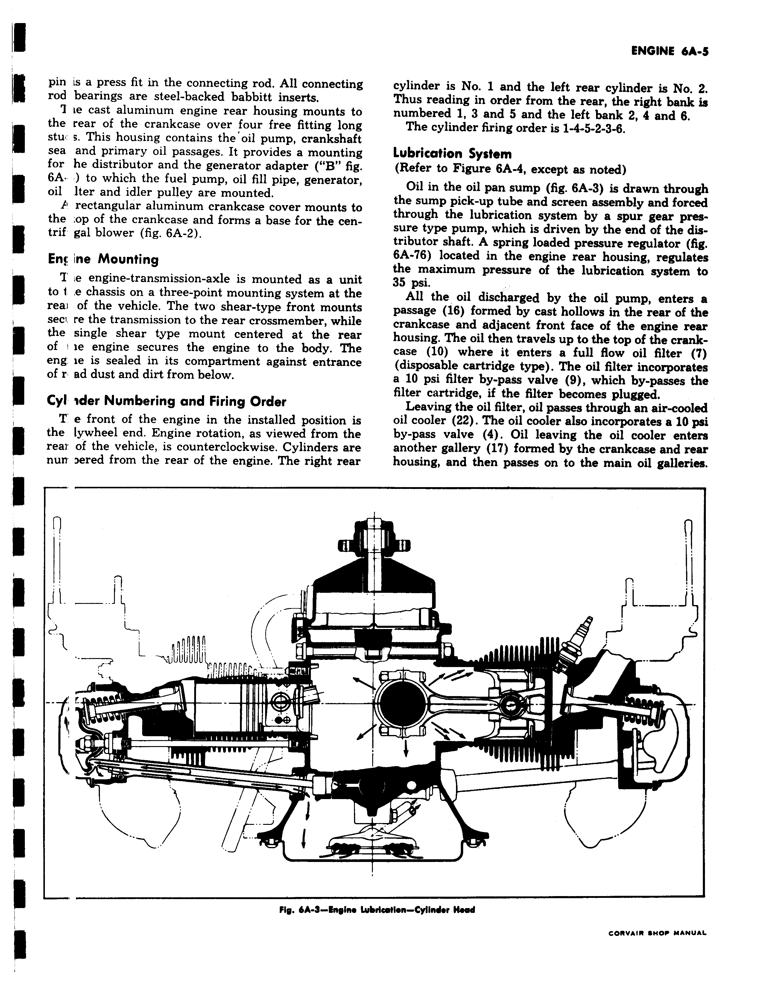
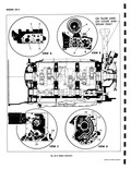
pin is a press fit in the connecting rod All connecting rod bearings are steel backed babbitt inserts 7 ie cast aluminum engine rear housing mounts to the rear of the crankcase over four free fitting long stu s This housing contains the oil pump crankshaft sea and primary oil passages It provides a mounting for he distributor and the generator adapter B fig 1 6A to which the fuel pump oil fill pipe generator fl oil lter and idler pulley are mounted E rectangular aluminum crankcase cover mounts to the op of the crankcase and forms a base for the centrif gal blower fig 6A 2 Enj fne Mounting T e engine transmission axle is mounted as a unit to 1 e chassis on a three point mounting system at the reaa of the vehicle The two shear type front mounts seci re the transmission to the rear crossmember while the single shear type mount centered at the rear of i ie engine secures the engine to the body The eng ie is sealed in its compartment against entrance of r ad dust and dirt from below Cyl ider Numbering and Firing Order T e front of the engine in the installed position is the lywheel end Engine rotation as viewed from the rear of the vehicle is counterclockwise Cylinders are nun Dered from the rear of the engine The right rear t u 1 N J 1 r Fig 6A 9 Engine cylinder is No 1 and the left rear cylinder is No 2 Thus reading in order from the rear the right bank is numbered 1 3 and 5 and the left bank 2 4 and 6 The cylinder firing order is 1 4 5 2 3 6 Lubrication System Refer to Figure 6A 4 except as noted Oil in the oil pan sump fig 6A 3 is drawn through the sump pick up tube and screen assembly and forced through the lubrication system by a spur gear pressure type pump which is driven by the end of the distributor shaft A spring loaded pressure regulator fig 6A 76 located in the engine rear housing regulates the maximum pressure of the lubrication system to 35 psi All the oil discharged by the oil pump enters a passage 16 formed by cast hollows in the rear of the crankcase and adjacent front face of the engine rear housing The oil then travels up to the top of the crankcase 10 where it enters a full flow oil filter T disposable cartridge type The oil filter incorporates a 10 psi filter by pass valve 9 which by passes the filter cartridge if the filter becomes plugged Leaving the oil filter oil passes through an air cooled oil cooler 22 The oil cooler also incorporates a 10 psi by pass valve 4 Oil leaving the oil cooler enters another gallery 1 formed by the crankcase and rear housing and then passes on to the main oil galleries fi l y v 1 Lubrication Cylinder Head