Jeep Parts Wiki | Ford Parts Wiki
Home | Search | Browse
Prev
 Next
Next
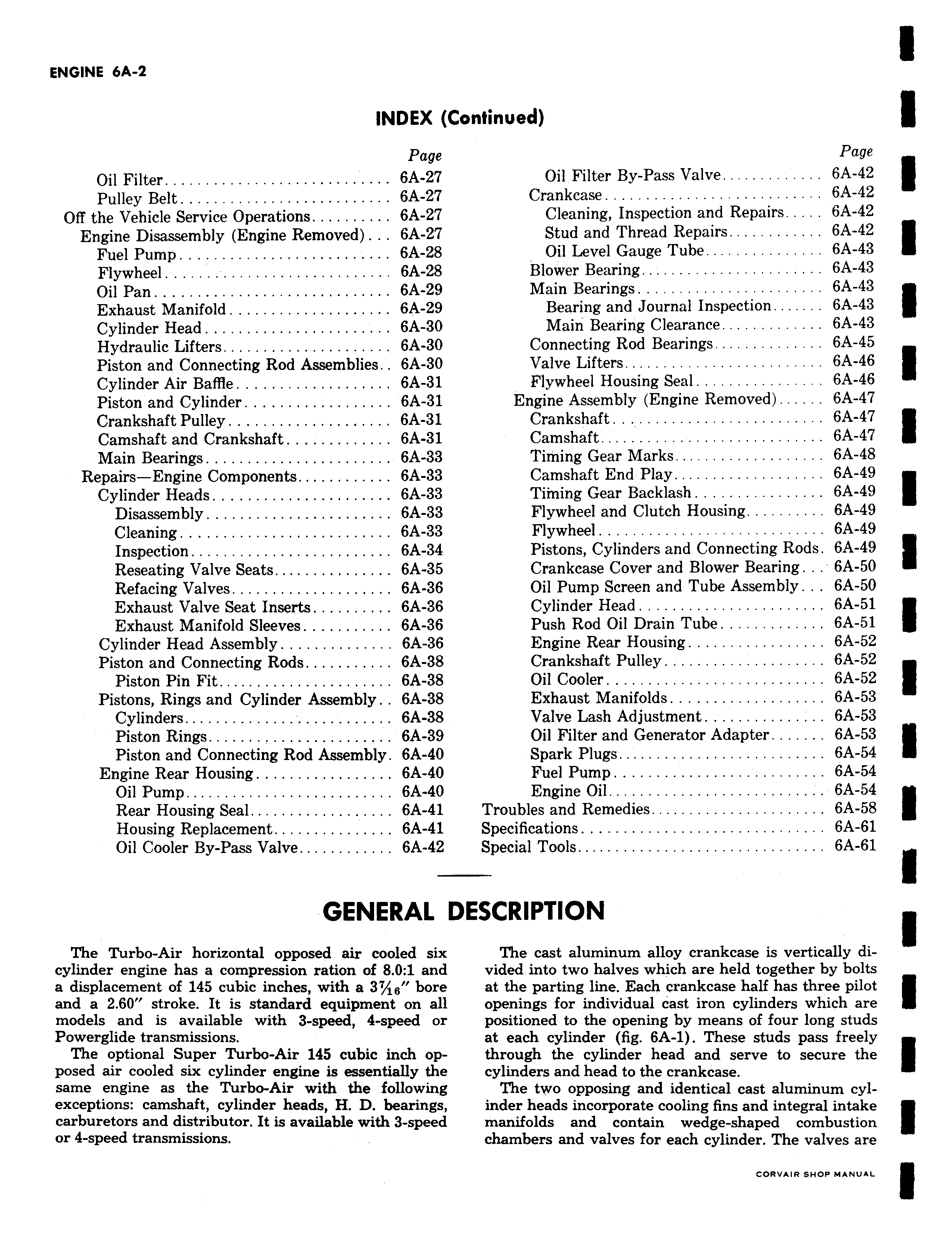
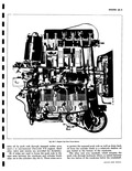
enUmt CA Z INDEX Page Oil Filter 6A 27 Pulley Belt 6A 27 Off the Vehicle Service Operations 6A 27 Engine Disassembly Engine Removed 6A 27 Fuel Pump 6A 28 Flywheel 6A 28 Oil Pan 6A 29 Exhaust Manifold 6A 29 Cylinder Head 6A 30 Hydraulic Lifters 6A 30 Piston and Connecting Rod Assemblies 6A 30 Cylinder Air Baffle 6A 31 Piston and Cylinder 6A 31 Crankshaft Pulley 6A 31 Camshaft and Crankshaft 6A 31 Main Bearings 6A 33 Repairs Engine Components 6A 33 Cylinder Heads 6A 33 Disassembly 6A 33 Cleaning 6A 33 Inspection 6A 34 Reseating Valve Seats 6A 35 Refacing Valves 6A 36 Exhaust Valve Seat Inserts 6A 36 Exhaust Manifold Sleeves 6A 36 Cylinder Head Assembly 6A 36 Piston and Connecting Rods 6A 38 Piston Pin Fit 6A 38 Pistons Rings and Cylinder Assembly 6A 38 Cylinders 6A 38 Piston Rings 6A 39 Piston and Connecting Rod Assembly 6A 40 Engine Rear Housing 6A 40 Oil Pump 6A 40 Rear Housing Seal 6A 41 Housing Replacement 6A 41 Oil Cooler By Pass Valve 6A 42 GENERAL I The Turbo Air horizontal opposed air cooled six cylinder engine has a compression ration of 8 0 1 and a displacement of 145 cubic inches with a 37 16 bore and a 2 60 stroke It is standard equipment on all models and is available with 3 speed 4 speed or Powerglide transmissions The optional Super Turbo Air 145 cubic inch opposed air cooled six cylinder engine is essentially the same engine as the Turbo Air with the following exceptions camshaft cylinder heads H D bearings carburetors and distributor It is available with 3 speed or 4 speed transmissions ontinued Page Oil Filter By Pass Valve 6A 42 Crankcase 6A 42 Cleaning Inspection and Repairs 6A 42 Stud and Thread Repairs 6A 42 Oil Level Gauge Tube 6A 43 Blower Bearing 6A 43 Main Bearings 6A 43 Bearing and Journal Inspection 6A 43 Main Bearing Clearance 6A 43 Connecting Rod Bearings 6A 45 Valve Lifters 6A 46 Flywheel Housing Seal 6A 46 Engine Assembly Engine Removed 6A 47 Crankshaft 6A 47 Camshaft 6A 47 Timing Gear Marks 6A 48 Camshaft End Play 6A 49 Timing Gear Backlash 6A 49 Flywheel and Clutch Housing 6A 49 Flywheel 6A 49 Pistons Cylinders and Connecting Rods 6A 49 Crankcase Cover and Blower Bearing 6A 50 Oil Pump Screen and Tube Assembly 6A 50 Cylinder Head 6A 51 Push Rod Oil Drain Tube 6A 51 Engine Rear Housing 6A 52 Crankshaft Pulley 6A 52 Oil Cooler 6A 52 Exhaust Manifolds 6A 53 Valve Lash Adjustment 6A 53 Oil Filter and Generator Adapter 6A 53 Spark Plugs 6A 54 Fuel Pump 6A 54 Engine Oi1 6A 54 Troubles and Remedies 6A 58 Specifications 6A 61 Special Tools 6A 61 ESCRIPTION The cast aluminum alloy crankcase is vertically divided into two halves which are held together by bolts at the parting line Each crankcase half has three pilot openings for individual cast iron cylinders which are positioned to the opening by means of four long studs at each cylinder fig 6A 1 These studs pass freely through the cylinder head and serve to secure the cylinders and head to the crankcase The two opposing and identical cast aluminum cylinder heads incorporate cooling fins and integral intake manifolds and contain wedge shaped combustion chambers and valves for each cylinder The valves are