Jeep Parts Wiki | Ford Parts Wiki
Home | Search | Browse
Prev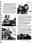
 Next
Next
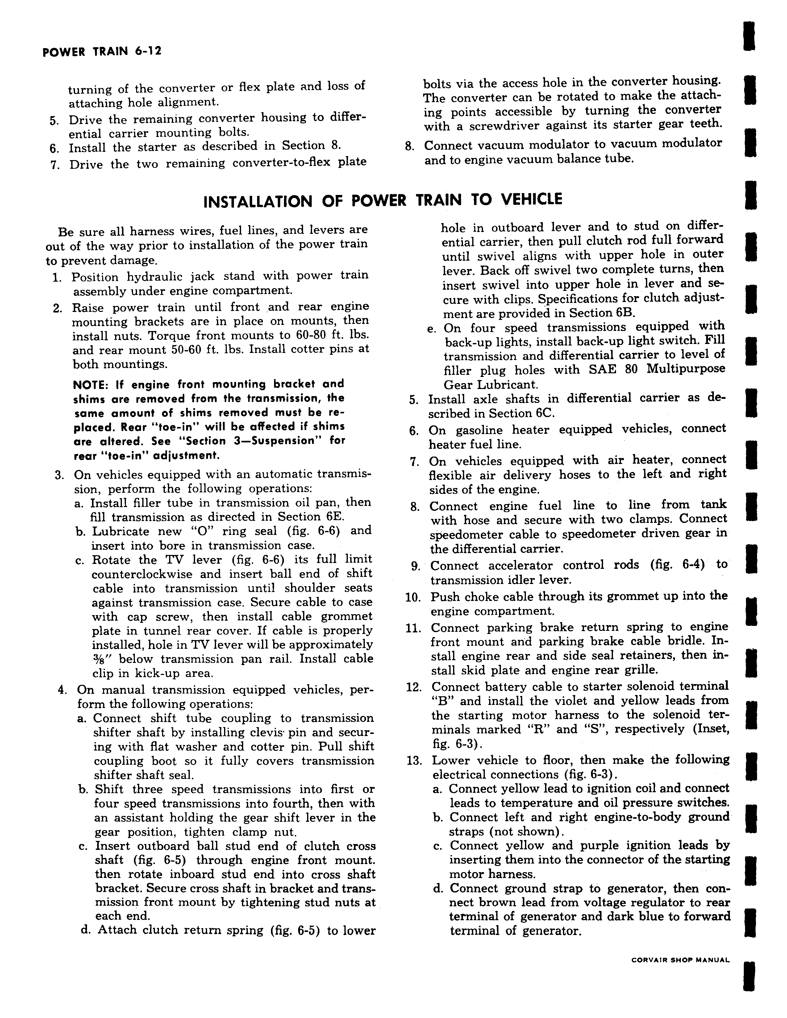
turning of the converter or flex plate and loss of attaching hole alignment 5 Drive the remaining converter housing to differential carrier mounting bolts 6 Install the starter as described in Section 8 7 Drive the two remaining converter to flex plate INSTALLATION OF PO Be sure all harness wires fuel lines and levers are out of the way prior to installation of the power train to prevent damage 1 Position hydraulic jack stand with power train assembly under engine compartment 2 Raise power train until front and rear engine mounting brackets are in place on mounts then install nuts Torque front mounts to 60 80 ft lbs and rear mount 50 60 ft lbs Install cotter pins at both mountings NOTE If engine front mounting bracket and shims are removed from the transmission the same amount of shims removed must be replaced Rear toe in will be affected if shims are altered See Section 3 Suspension for rear toe in adjustment 3 On vehicles equipped with an automatic transmission perform the following operations a Install filler tube in transmission oil pan then fill transmission as directed in Section 6E b Lubricate new O ring seal fig 6 6 and insert into bore in transmission case c Rotate the TV lever fig 6 6 its full limit counterclockwise and insert ball end of shift cable into transmission until shoulder seats against transmission case Secure cable to case with cap screw then install cable grommet plate in tunnel rear cover If cable is properly installed hole in TV lever will be approximately 3 e below transmission pan rail Install cable clip in kick up area 4 On manual transmission equipped vehicles perform the following operations a Connect shift tube coupling to transmission shifter shaft by installing clevis pin and securing with flat washer and cotter pin Pull shift coupling boot so it fully covers transmission shifter shaft seal b Shift three speed transmissions into first or four speed transmissions into fourth then with an assistant holding the gear shift lever in the gear position tighten clamp nut c Insert outboard ball stud end of clutch cross shaft fig 6 5 through engine front mount then rotate inboard stud end into cross shaft bracket Secure cross shaft in bracket and transmission front mount by tightening stud nuts at each end d Attach clutch return spring fig 6 5 to lower bolts via the access hole in the converter housing The converter can be rotated to make the attaching points accessible by turning the converter with a screwdriver against its starter gear teeth 8 Connect vacuum modulator to vacuum modulator and to engine vacuum balance tube rIVER TRAIN TO VEHICLE hole in outboard lever and to stud on differential carrier then pull clutch rod full forward until swivel aligns with upper hole in outer lever Back off swivel two complete turns then insert swivel into upper hole in lever and secure with clips Specifications for clutch adjustment are provided in Section 6B e On four speed transmissions equipped with back up lights install back up light switch Fill transmission and differential carrier to level of filler plug holes with SAE 80 Multipurpose Gear Lubricant 5 Install axle shafts in differential carrier as described in Section 6C 6 On gasoline heater equipped vehicles connect heater fuel line 7 On vehicles equipped with air heater connect flexible air delivery hoses to the left and right sides of the engine 8 Connect engine fuel line to line from tank with hose and secure with two clamps Connect speedometer cable to speedometer driven gear in the differential carrier 9 Connect accelerator control rods fig 6 4 to transmission idler lever 10 Push choke cable through its grommet up into the engine compartment 11 Connect parking brake return spring to engine front mount arid parking brake cable bridle Install engine rear and side seal retainers then install skid plate and engine rear grille 12 Connect battery cable to starter solenoid terminal B and install the violet and yellow leads from the starting motor harness to the solenoid ter minals marked R and S respectively Inset fig 6 3 13 Lower vehicle to floor then make the following electrical connections fig 6 3 a Connect yellow lead to ignition coil and connect leads to temperature and oil pressure switches b Connect left and right engine to body ground straps not shown c Connect yellow and purple ignition leads by inserting them into the connector of the starting motor harness d Connect ground strap to generator then connect brown lead from voltage regulator to rear terminal of generator and dark blue to forward terminal of generator