Jeep Parts Wiki | Ford Parts Wiki
Home | Search | Browse
Prev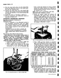
 Next
Next
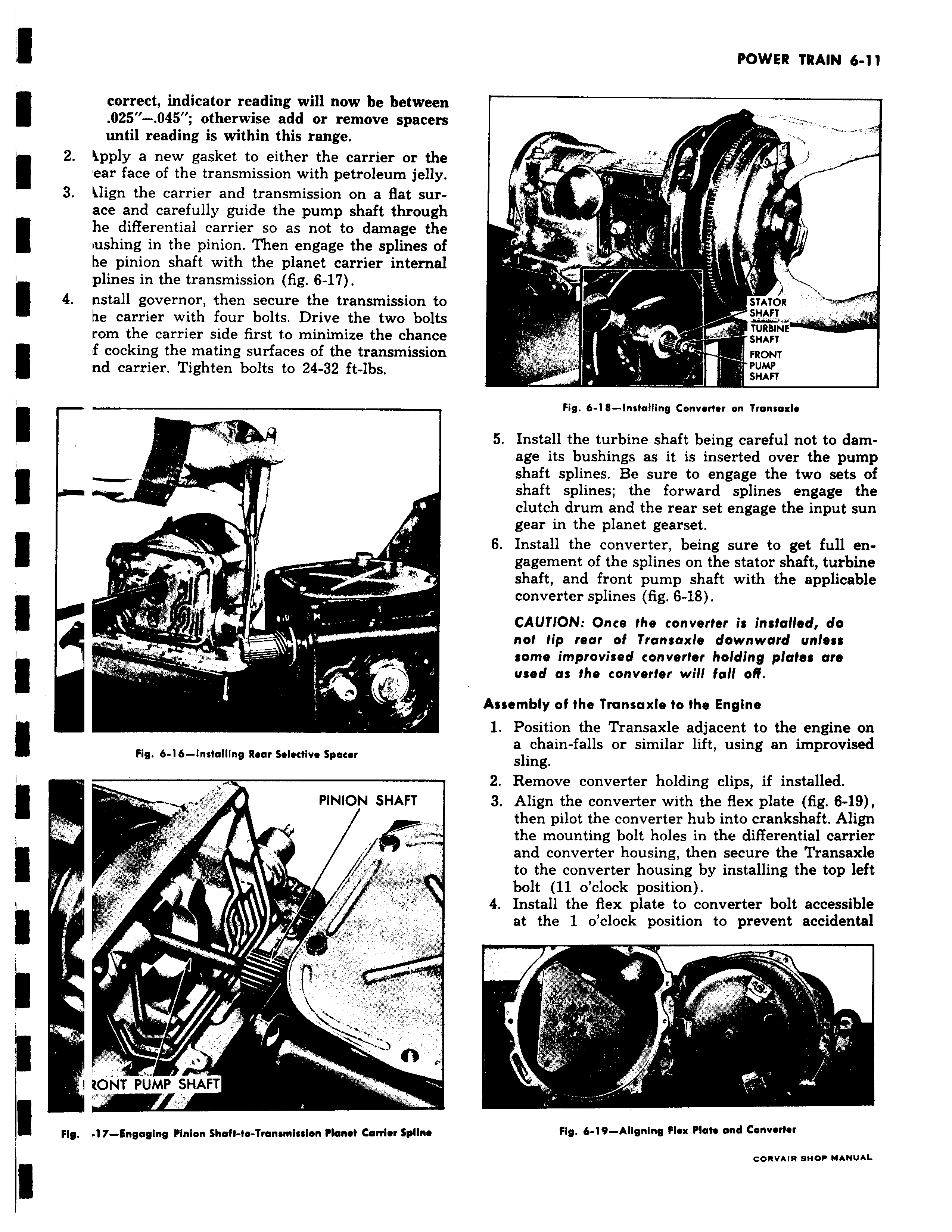
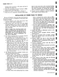
correct indicator reading will now be between 025 045 otherwise add or remove spacers until reading is within this range 2 kpply a new gasket to either the carrier or the ear face of the transmission with petroleum jelly 3 klign the carrier and transmission on a flat surace and carefully guide the pump shaft through t he differential carrier so as not to damage the f lushing in the pinion Then engage the splines of he pinion shaft with the planet carrier internal plines in the transmission fig 6 17 I 4 nstall governor then secure the transmission to he carrier with four bolts Drive the two bolts rom the carrier side first to minimize the chance r f cocking the mating surfaces of the transmission f nd carrier Tighten bolts to 24 32 ft lbs r Noma Fig 6 16 Installing Rear Selective Spacer PINION SHAFT lr y W I RONT PUMP SHAFT Fig 17 Engaging Pinion Shaft to Transi ission Planet Carrier Spline 7 Y STATOR SHAFT x TURBINE SHAFT FRONT PUMP SHAFT Fig 6 18 installing Convertor an Tronsaxle 5 Install the turbine shaft being careful not to damage its bushings as it is inserted over the pump shaft splines Be sure to engage the two sets of shaft splines the forward splines engage the clutch drum and the rear set engage the input sun gear in the planet gearset 6 Install the converter being sure to get full engagement of the splines on the stator shaft turbine shaft and front pump shaft with the applicable converter splines fig 6 18 CAUTION Once the converter is installed do not tip rear of Transaxle downward unless some improvised converter holding plates are used as the converter will fall 011 Assembly of the Transaxle to the Engine 1 Position the Transaxle adjacent to the engine on a chain falls or similar lift using an improvised sling 2 Remove converter holding clips if installed 3 Align the converter with the flex plate fig 6 19 then pilot the converter hub into crankshaft Align the mounting bolt holes in the differential carrier and converter housing then secure the Transaxle to the converter housing by installing the top left bolt 11 o clock position 4 Install the flex plate to converter bolt accessible at the 1 o clock position to prevent accidental z Fig 6 19 Aligning Flex Plate and Converter CORVAIR SHOP MANUAL