Jeep Parts Wiki | Ford Parts Wiki
Home | Search | Browse | Marketplace | Messages | FAQ | Guest
Prev

 Next
Next
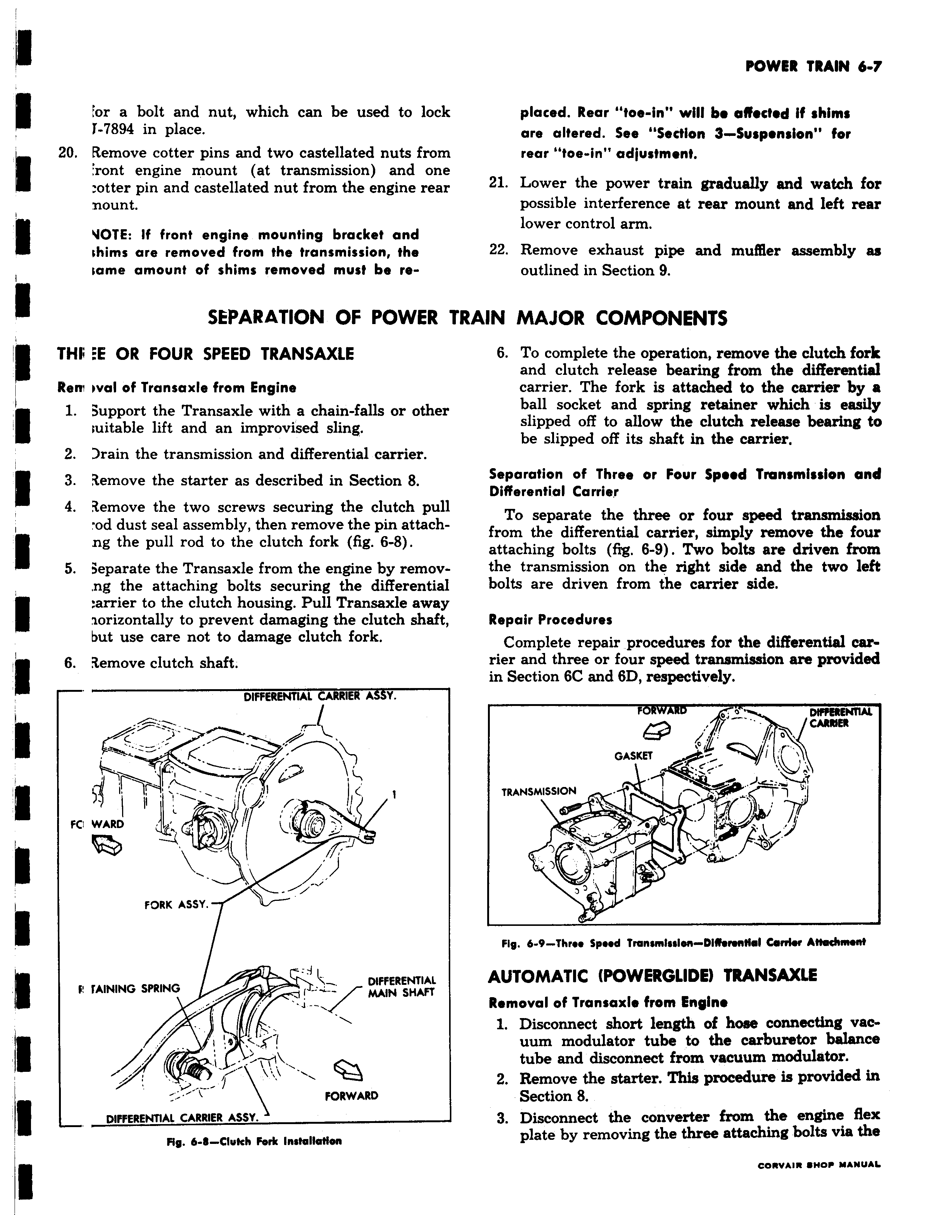
or a bolt and nut which can be used to lock i 7894 in place 20 Remove cotter pins and two castellated nuts from ront engine mount at transmission and one otter pin and castellated nut from the engine rear nount VOTE If front engine mounting bracket and shims are removed from the transmission the tame amount of shims removed must be reSEPARATION OF POWER 1 THf E OR FOUR SPEED TRANSAXLE Rem oval of Transaxle from Engine 1 3upport the Transaxle with a chain falls or other luitable lift and an improvised sling 2 rain the transmission and differential carrier 3 1emove the starter as described in Section 8 4 3emove the two screws securing the clutch pull od dust seal assembly then remove the pin attachng the pull rod to the clutch fork fig 6 8 5 3eparate the Transaxle from the engine by remov ng the attaching bolts securing the differential arrier to the clutch housing Pull Transaxle away zorizontally to prevent damaging the clutch shaft but use care not to damage clutch fork 6 3emove clutch shaft DIFFERENTIAL CARRIER A 99Y h 71 6 FC WARD FORK ASSY i i F fAINING SPRING DIFFERENTIAL MAIN SHAFT 1r I I 9 I FORWARD DIFFERENTIAL CARRIER ASSY Fig 6 8 Clukh Fork Installation placed Rear toe in will b affected if shims are altered See Section 3 Suspension for rear toe in adjustment 21 Lower the power train gradually and watch for possible interference at rear mount and left rear lower control arm 22 Remove exhaust pipe and muffler assembly as outlined in Section 9 rRAIN MAJOR COMPONENTS 6 To complete the operation remove the clutch fork and clutch release bearing from the differential carrier The fork is attached to the carrier by a ball socket and spring retainer which is easily slipped off to allow the clutch release bearing to be slipped off its shaft in the carrier Separation of Three or Four Speed Transmission and Differential Carrier To separate the three or four speed transmission from the differential carrier simply remove the four attaching bolts fig 6 9 Two bolts are driven from the transmission on the right side and the two left bolts are driven from the carrier side Repair Procedures Complete repair procedures for the differential carrier and three or four speed transmission are provided in Section 6C and 6D respectively FORWARD DffBENTIAL CARRIER GASKET v TRANSMISSION Fig 6 9 Three Speed Transmission DIMnnNal Corder Attachment AUTOMATIC POWERGLIDE TRANSAXLE Removal of Transaxle from Engine 1 Disconnect short length of hose connecting vacuum modulator tube to the carburetor balance tube and disconnect from vacuum modulator 2 Remove the starter This procedure is provided in Section 8 3 Disconnect the converter from the engine flex plate by removing the three attaching bolts via the

 Next
Next