Jeep Parts Wiki | Ford Parts Wiki
Home | Search | Browse
|
Corvette Assembly Manual January 1978 |
|
Prev
 Next
Next
464887
464887
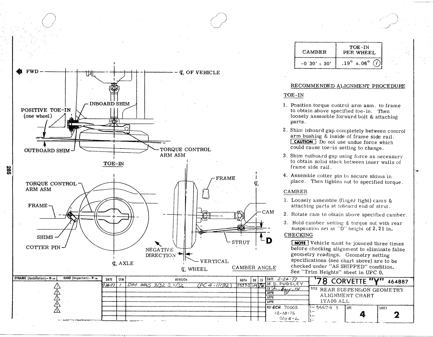
A A E CAMBER PER WHEEL il 0 so xo 1s a 0s C FWD eg or vm ncms J 1 RECOMMENDED A LlGNMEN 1 PROCEDURE TOE IN INBOARD SHIM 1 Position torque control arm asm to frame POSITIVE I OE IN to obtain above specified toe in Then une wheel A loosely assemhle forward ben sl attaching l Wl parts 4 E r 2 shim mnmm gap completely between control arm bushing inside of Irame side rail Do not use undue force which OUTBOARD SHTM TORQUE CONTROL could cause t0e in setting to change I ARM ASM 3 Shim outboard gap using force as necessarv l to obtain solid stack between inner walls oi E frame side mn l FRAME I 4 Assemble cotter pin to secure shixns in lace Then ti iten nut to s e I cl tor Tomasz comaoi fi g P le que ARM ASM CAMBER r c e V 1 Loosely assemble finger tight cams FRAME IF V CAM attaching parts al inbmard and oi strut j l 2 Rotate cam to obtain above specified camber c ll s Hold czimbcr setting s torque nut with wear suspension sel at D height oi 2 21 in CHECKING SHl MS STRUT D Kill Vehicle must he jouncecl three times COTTER PIN NEGATIVE before checking alignment to eliminate false Dyggcjqgy geonieltry readings Geometry setting Q AXLE 4 VERTICAL specifications see chant above are to be Q WHEEL CAMBER ANGLE checxed under AS SHIPPED condition See Trim Heigms sheet in npc 0 nwnuu illmurlinnny A umn inmpulltil n m TM I m m J 7 0 5 Zgiggicv CORVETTE Y 464887 I s e S E 3 YH Am Aiitswmtvmsr cnAn r inn IYAOG ALL Q MR me MM 5 s QQ z us rs l 4 2 o IH i 4 1 tj