Jeep Parts Wiki | Ford Parts Wiki
Home | Search | Browse | Marketplace | Messages | FAQ | Guest
|
Corvette Assembly Manual January 1978 |
|
Prev
 Next
Next
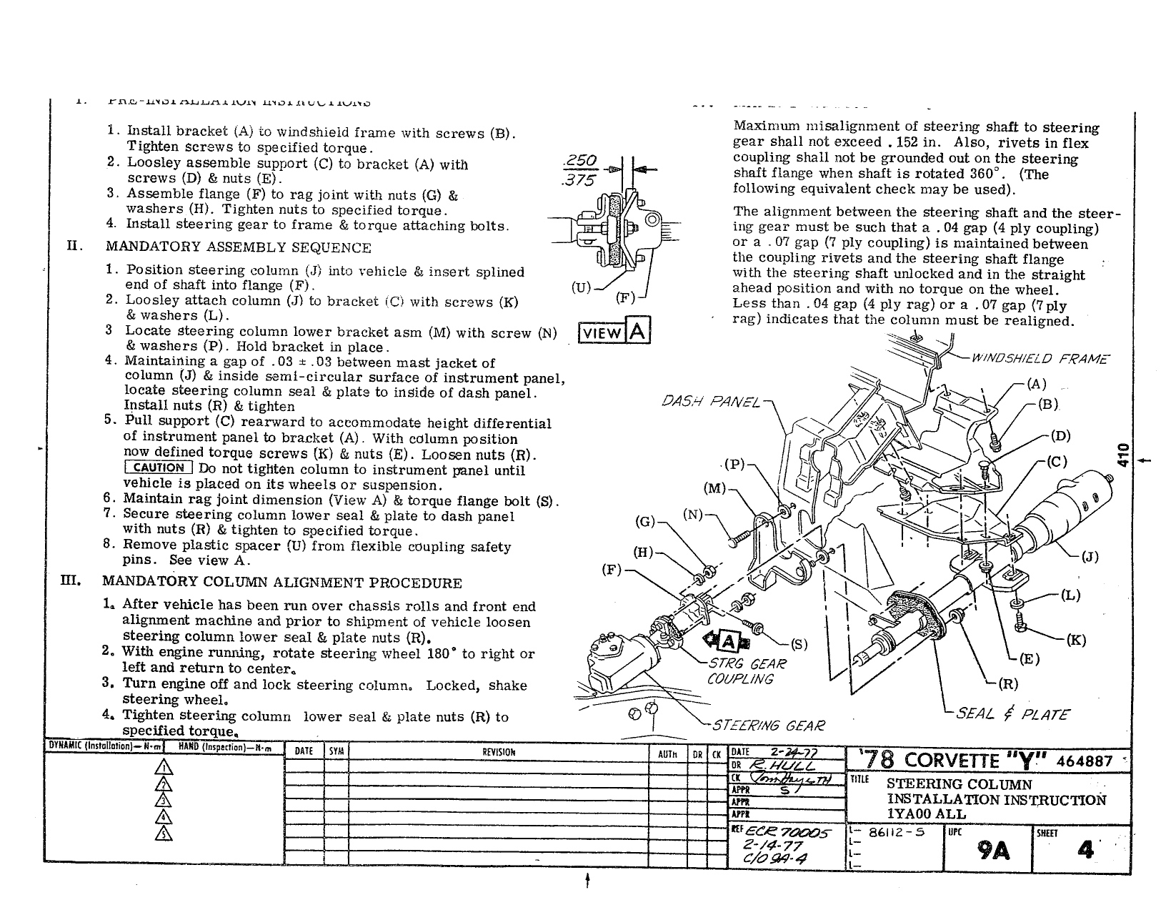
M xl l t f t hart to t 1 Install bracket A to winnehiela frame with screws la ge Shu 1 ifegilgo nvm ineaglg T Screws 0 Sv r 4 250 coupling Sinn not be grounded en on the steering 2 Loosley assemble support C to bracket A with 1 shan Hangs when Shan is rotated 3g0 The screws D nuts E V 4375 following equivalent check may be used 3 Assemble flange F to rag ioint with nuts G I WVU washers H Tighten nuts to specified torque 1 he alignment between the steering shaft and the steer 4 Install steering gear to frame torque attaching bolts req 5 ing gea muszrrbelsuch that ag 04 gapt 4 plgkcotixipling IL MANDATORY ASSEMBLY SEQUENCE gk Sfeacouplggg rivgtg gFtl gste ei5i1i gnsharft flafigeeen 1 Position steering column J into veinele 4 insert splined with the steering shaft unlocked and in the Straight end 0 Shaft min flange FL U F ahead position and with no torque on the wheel 2 Loosley attach column J to bracket ic with screws K Les than 04 gap 4 ply ras r 3 07 e p1 7p1y 3 washers L rag indicates that the column must be rea igned 3 Locate steering column lower bracket asm M with screw N VIEW A mi washers P Hold bracket in place t t 4 Maintaining a gap of 03 e 03 between mast jacket of WW05 l ELO QAM column J inside semi circular surface of instrument panel 1 A locate steering column seal plate to inside of dash panel Install nuts R tighten D EW PANEL B 5 Pull support C rearward to accommodate height differential Q fx D of mstrument panel to bracket A With column position 5 g q now defined torque screws K nuts E Loosen nuts R P V Q E C Q CAUTION Do not tighten column to instrument panel until I QI P s vehicle is placed on its wheels or suspension M is 2 i 6 Maintain rag joint dimension View A torque flange bolt S 7 Secure steering column lower seal plate to dash panel G N ii with nuts R tighten to specified torque L 8 Remove plastic spacer U from flexible coupling safety H I 1 E J pins ee view A F s E H MANDATORY COLUMN ALIGNMENT PROCEDURE M a L 1 After vehicle has been run over chassis rolls and front end Qfy X aligrunent machine and prior to shipment of vehicle loosen 5 W i il steering column lower seal Si plate nuts R i S K 2 With engine running rotate steering wheel l8D to right or 5 6 654 e E left and return to center OUP V6 R 3 Turn engine off and lock steering cnlui nn Locked shake steering wheel 4 Tighten steering column lower seal Ke plate nuts R to 5 2 F N6 G AE SEAL Pbqrf specified torque ml sw ImIl il m 5 73 convgng YF lunar i g 1E 1EE l lm srcrmuc commu 1 INSTALLATION msrizucrion yA00 ALL A 1 1 m Lg E E76UU5 B5 5 Z 77 tz E ggg 4 i 1