Jeep Parts Wiki | Ford Parts Wiki
Home | Search | Browse
Prev

 Next
Next
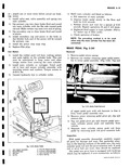
Installation 1 Pass end of cable and conduit tip through flange plate entry hole making sure that conduit locking fingers all expand fully 2 Compress retaining spring and position cable in U shaped actuating lever junction 3 Replace bearing retainer retainer bolts universal joint U bolts brake drum and wheel 4 Pass die cast conduit tip through support bracket and secure with retainer clip 5 Position rubber boot over conduit tip carefully indexing bead of boot in groove provided in tip casting 6 Attach clevis to equalizer assembly with cotter pin 7 Proceed as outlined under Parking Brake Adjustment SERVICE BRAKES Brake Shoes Brake Drums Wheel Cylinders Although larger in size the service brakes used on this vehicle are basically of the same design as those used on the Corvair passenger car and are serviced in much the same manner For disassembly inspection and assembly procedures used for service of brake shoes drums and wheel cylinders refer to appropriate heading under Corvair Service Operations Note however that rear wheel cylinders are retained by two capscrews which pass through the flange plate thus removal of anchor pin is not necessary for removal of wheel cylinder Upon installation of rear wheel cylinders torque retaining screws 11 19 ft lbs Also note that front brake drums are removed in the same way as the rear drums Consult specifications section for component dimensions MAIN CYLINDER Fig 5 33 Removal 1 From under vehicle remove hydraulic line from main cylinder outlet 2 Remove four capscrews and washers retaining main cylinder to outrigger 3 Remove main cylinder from vehicle Disassembly 1 Place main cylinder assembly in a vise push rod end up 2 Remove push rod boot and flange gasket 3 Remove piston stop snap ring and piston from main cylinder 4 Remove the primary cup spring valve assembly and valve seat s 5 1 3 2 3 4 15 6 7 8 9 10 11 12 Fig 5 33 Cross Section of Main Cylindw 1 Push Rod Boot 9 Secondary Piston Cup 2 Push Rod 10 Piston 3 Piston Retaining Ring 11 Primary Piston Cup 4 Filler Cap 12 Piston Return Spring 5 Filler Cap Gasket 13 Fluid Inlet 6 Check Valve 14 Compensating Port 7 Check Valve Seat 15 Cylinder Casting 8 Fluid Outlet 5 Remove filler plug from top of main cylinder 6 Remove secondary cup from piston Inspection 1 Wash all parts in clean alcohol Make sure that compensating port in main cylinder body and bleeder holes in piston are clean and open NOTE Before washing parts hands must be dean Do not wash hands in gasoline or fuel oil before cleaning parts Use soap and water to clean hands 2 Inspect cylinder bore to make sure it is smooth 3 Inspect primary and secondary cups valve and valve seat for damage or swelling Swelling of rubber parts is due to the use of contaminated brake fluid or washing parts in gasoline or kerosene NOTE The primary cup has a brass support ring vulcanized in its base to prevent it from imbedding in the bleeder holes during braking action 4 Check piston fit in cylinder bore fig 5 21 The clearance between piston and wall of the cylinder should be from 001 005 Assembly Whenever a hydraulic brake main cylinder is overhauled care must be taken to reassemble the valve and seat correctly Improper assembly of the check valve seat rubber washer will result in its distortion When the check valve seat is distorted there will be no check valve seal and there will be a loss of brake pedal travel also the pedal will have to be depressed