Jeep Parts Wiki | Ford Parts Wiki
Home | Search | Browse
Prev
 Next
Next
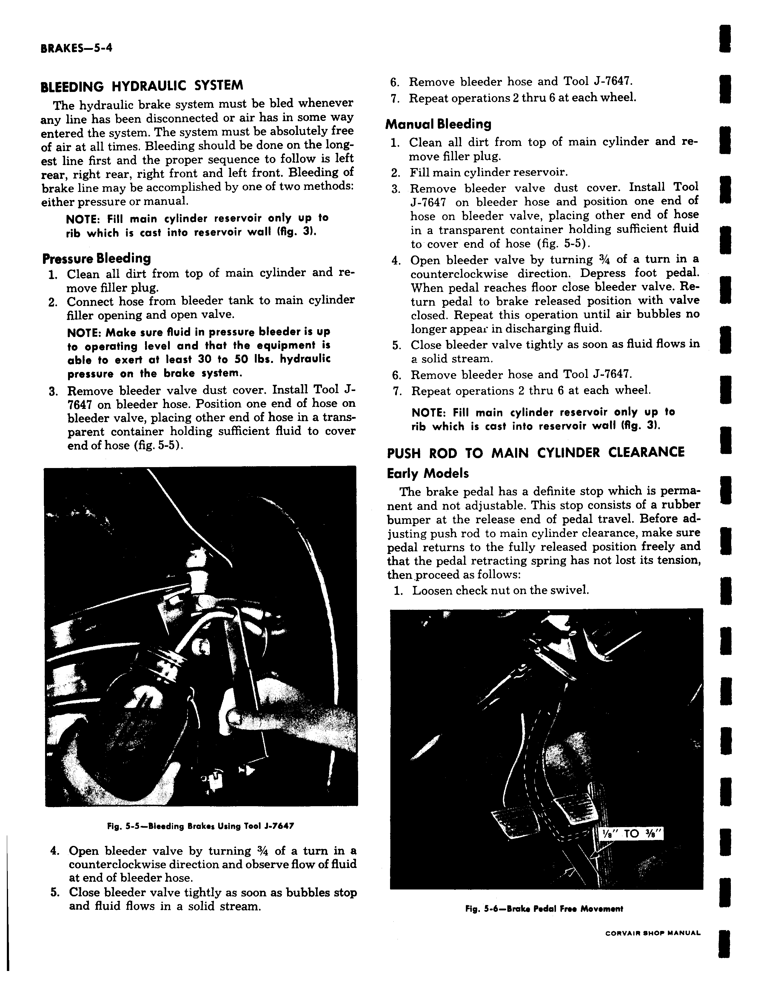
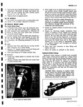
BLEEDING HYDRAULIC SYSTEM The hydraulic brake system must be bled whenever any line has been disconnected or air has in some way entered the system The system must be absolutely free of air at all times Bleeding should be done on the longest line first and the proper sequence to follow is left rear right rear right front and left front Bleeding of brake line may be accomplished by one of two methods either pressure or manual NOTE Fill main cylinder reservoir only up to rib which is cast into reservoir wall fig 3 Pressure Bleeding 1 Clean all dirt from top of main cylinder and remove filler plug 2 Connect hose from bleeder tank to main cylinder filler opening and open valve NOTE Make sure fluid in pressure bleeder is up to operating level and that the equipment is able to exert at least 30 to 50 Ibs hydraulic pressure on the brake system 3 Remove bleeder valve dust cover Install Tool J7647 on bleeder hose Position one end of hose on bleeder valve placing other end of hose in a transparent container holding sufficient fluid to cover end of hose fig 5 5 1 Fig 5 5 Bleeding Brakes Using Tool J 7647 4 Open bleeder valve by turning 3 4 of a turn in a counterclockwise direction and observe flow of fluid at end of bleeder hose 5 Close bleeder valve tightly as soon as bubbles stop and fluid flows in a solid stream 6 Remove bleeder hose and Tool J 7647 7 Repeat operations 2 thru 6 at each wheel Manual Bleeding 1 Clean all dirt from top of main cylinder and remove filler plug 2 Fill main cylinder reservoir 3 Remove bleeder valve dust cover Install Tool J 7647 on bleeder hose and position one end of hose on bleeder valve placing other end of hose in a transparent container holding sufficient fluid to cover end of hose fig 5 5 4 Open bleeder valve by turning 3 4 of a turn in a counterclockwise direction Depress foot pedal When pedal reaches floor close bleeder valve Re turn pedal to brake released position with valve closed Repeat this operation until air bubbles no longer appeau in discharging fluid 5 Close bleeder valve tightly as soon as fluid flows in a solid stream 6 Remove bleeder hose and Tool J 647 7 Repeat operations 2 thru 6 at each wheel NOTE Fill main cylinder reservoir only up to rib which is cast into reservoir wall fig 3 PUSH ROD TO MAIN CYLINDER CLEARANCE Early Models The brake pedal has a definite stop which is permanent and not adjustable This stop consists of a rubber bumper at the release end of pedal travel Before adjusting push rod to main cylinder clearance make sure pedal returns to the fully released position freely and that the pedal retracting spring has not lost its tension then proceed as follows 1 Loosen check nut on the swivel i a TO 3 e Fig 5 6 Broke Pedal Free Movement