Jeep Parts Wiki | Ford Parts Wiki
Home | Search | Browse
Prev

 Next
Next
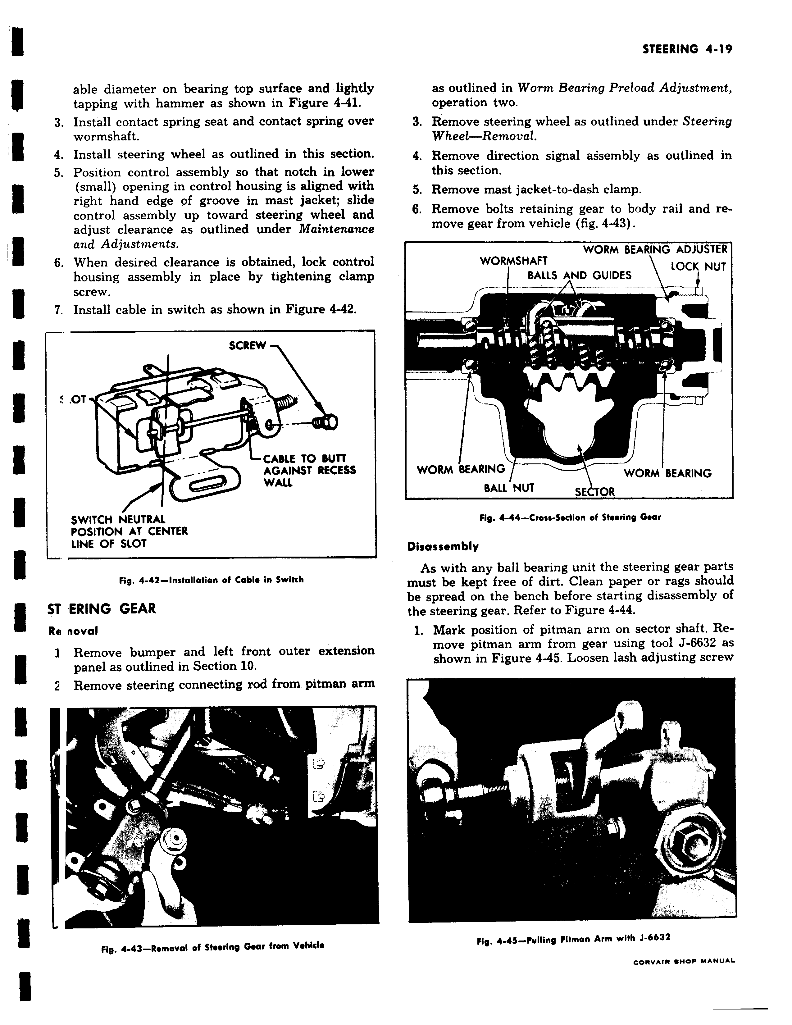
able diameter on bearing top surface and lightly tapping with hammer as shown in Figure 4 41 3 Install contact spring seat and contact spring over wormshaft 4 Install steering wheel as outlined in this section 5 Position control assembly so that notch in lower small opening in control housing is aligned with right hand edge of groove in mast jacket slide control assembly up toward steering wheel and adjust clearance as outlined under Maintenance and Adjustments 6 When desired clearance is obtained lock control housing assembly in place by tightening clamp I screw 7 Install cable in switch as shown in Figure 4 42 SCREW OT I ty w CABLE TO BUTT AGAINST RECESS 1 WALL SWITCH NEUTRAL POSITION AT CENTER LINE OF SLOT Fig 4 42 Installation of Cable in Switch ST ERING GEAR Re noval 1 Remove bumper and left front outer extension panel as outlined in Section 10 2 Remove steering connecting rod from pitman arm r I i j Fig 4 43 Romoval of Steering War from Vehicle as outlined in Worm Bearing Preload Adjustment operation two 3 Remove steering wheel as outlined under Steering Wheel Removal 4 Remove direction signal assembly as outlined in this section 5 Remove mast jacket to dash clamp 6 Remove bolts retaining gear to body rail and remove gear from vehicle fig 4 43 WORM BEARING ADJUSTER WORMSHAFT LOCK NUT BALLS AND GUIDES r WORM BEARING WORM BEARING BALL NUT SE TOR Fig 4 44 Cross Section of Steering Gear Disassembly As with any ball bearing unit the steering gear parts must be kept free of dirt Clean paper or rags should be spread on the bench before starting disassembly of the steering gear Refer to Figure 4 44 1 Mark position of pitman arm on sector shaft Remove pitman arm from gear using tool J 6632 as shown in Figure 4 45 Loosen lash adjusting screw T Fig 4 43 Pulling Pitman Arm with J 663Z CORVAIR SHOP MANUAL

 Next
Next