Jeep Parts Wiki | Ford Parts Wiki
Home | Search | Browse
Prev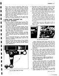
 Next
Next
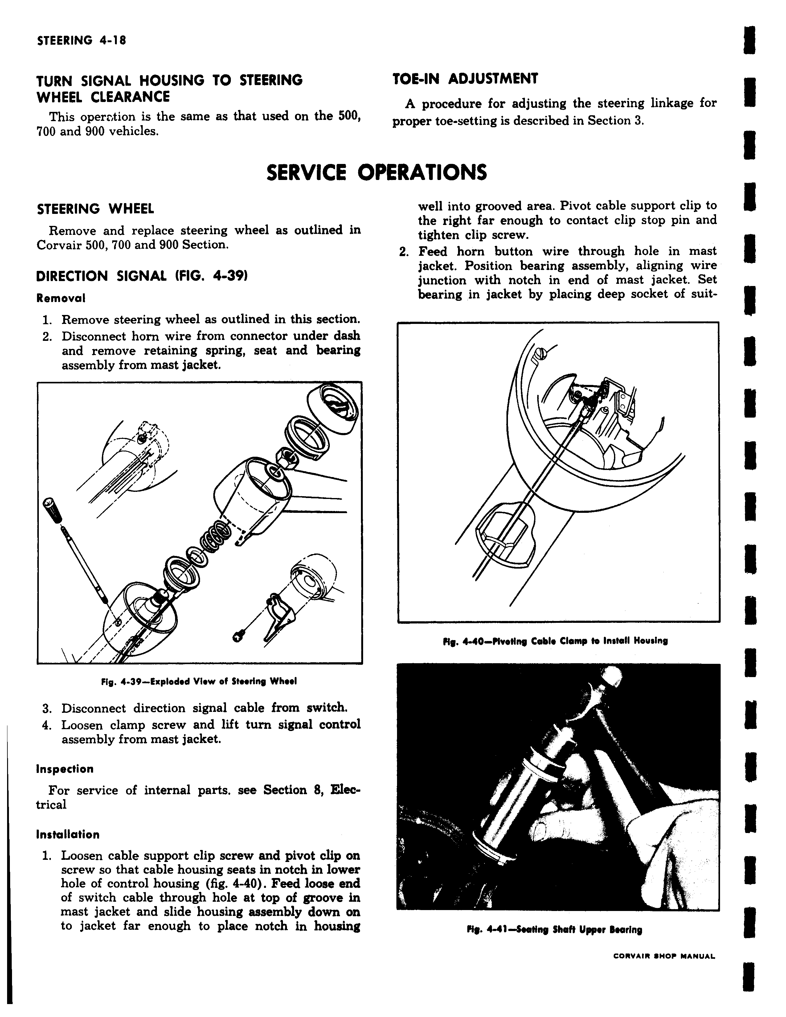
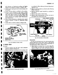
TURN SIGNAL HOUSING TO STEERING WHEEL CLEARANCE This operr tion is the same as that used on the 500 700 and 900 vehicles SERVICE O STEERING WHEEL Remove and replace steering wheel as outlined in Corvair 500 700 and 900 Section DIRECTION SIGNAL FIG 4 39 Removal 1 Remove steering wheel as outlined in this section 2 Disconnect horn wire from connector under dash and remove retaining spring seat and bearing assembly from mast jacket 1 ov O i Fig 4 39 Exploded View of Steering Wheel 3 Disconnect direction signal cable from switch 4 Loosen clamp screw and lift turn signal control assembly from mast jacket Inspection For service of internal parts see Section 8 Electrical Installation 1 Loosen cable support clip screw and pivot clip on screw so that cable housing seats in notch in lower hole of control housing fig 4 40 Feed loose end of switch cable through hole at top of groove in mast jacket and slide housing assembly down on to jacket far enough to place notch in housing TOE IN ADJUSTMENT A procedure for adjusting the steering linkage for proper toe setting is described in Section 3 PERATIONS well into grooved area Pivot cable support clip to the right far enough to contact clip stop pin and tighten clip screw 2 Feed horn button wire through hole in mast jacket Position bearing assembly aligning wire junction with notch in end of mast jacket Set bearing in jacket by placing deep socket of suit0 N M40 MveNny Cable Clamp to Install Housing r Mg 4 41 SwNRg Shaft Upper Bearing CORVAIR HOP MANUAL