Jeep Parts Wiki | Ford Parts Wiki
Home | Search | Browse | Marketplace | Messages | FAQ | Guest
Prev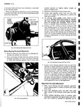
 Next
Next
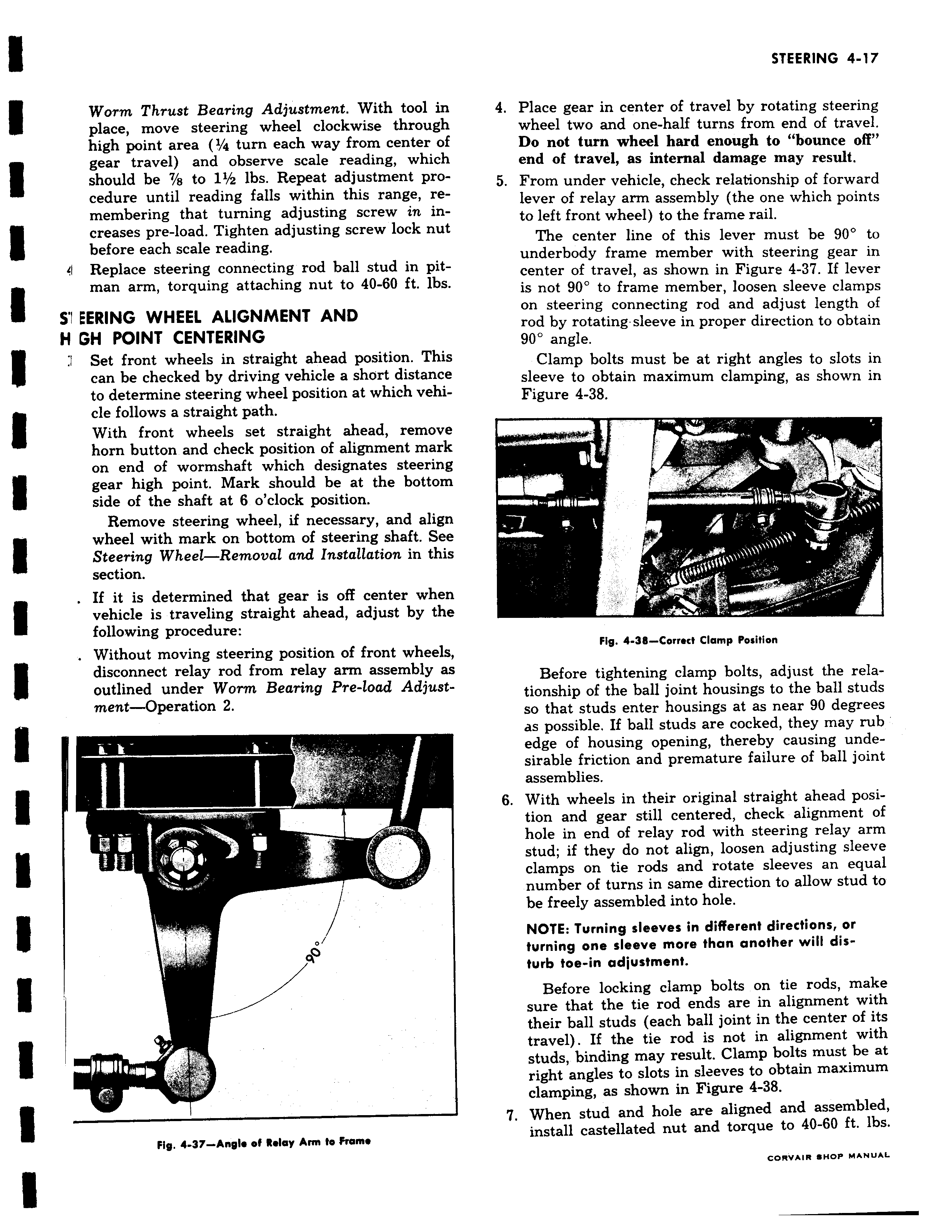
Worm Thrust Bearing Adjustment With tool in place move steering wheel clockwise through high point area 1 4 turn each way from center o1 gear travel and observe scale reading which should be 7 s to 11 2 lbs Repeat adjustment procedure until reading falls within this range remembering that turning adjusting screw in increases pre load Tighten adjusting screw lock nut before each scale reading 41 Replace steering connecting rod ball stud in pitman arm torquing attaching nut to 40 60 ft lbs S I EERING WHEEL ALIGNMENT AND H GH POINT CENTERING 1 Set front wheels in straight ahead position Thi can be checked by driving vehicle a short distance to determine steering wheel position at which vehicle follows a straight path With front wheels set straight ahead remove horn button and check position of alignment mark on end of wormshaft which designates steering gear high point Mark should be at the bottom side of the shaft at 6 o clock position Remove steering wheel if necessary and align wheel with mark on bottom of steering shaft See t Steering Wheel Removal and Installation in this section If it is determined that gear is off center when f vehicle is traveling straight ahead adjust by the following procedure Without moving steering position of front wheels disconnect relay rod from relay arm assembly as outlined under Worm Bearing Pre load Adjustment Operation 2 I q Fig 4 37 Angle of Relay Ann to Frame 4 Place gear in center of travel by rotating steering wheel two and one half turns from end of travel Do not turn wheel hard enough to bounce off end of travel as internal damage may result 5 From under vehicle check relationship of forward lever of relay arm assembly the one which points to left front wheel to the frame rail The center line of this lever must be 90 to underbody frame member with steering gear in center of travel as shown in Figure 4 37 If lever is not 90 to frame member loosen sleeve clamps on steering connecting rod and adjust length of rod by rotating sleeve in proper direction to obtain 90 angle Clamp bolts must be at right angles to slots in sleeve to obtain maximum clamping as shown in Figure 4 38 I I i I j Fig 4 38 Correct Clamp Position Before tightening clamp bolts adjust the relationship of the ball joint housings to the ball studs so that studs enter housings at as near 90 degrees as possible If ball studs are cocked they may rub edge of housing opening thereby causing undesirable friction and premature failure of ball joint assemblies 6 With wheels in their original straight ahead position and gear still centered check alignment of hole in end of relay rod with steering relay arm stud if they do not align loosen adjusting sleeve clamps on tie rods and rotate sleeves an equal number of turns in same direction to allow stud to be freely assembled into hole NOTE Turning sleeves in different directions or turning one sleeve more than another will disturb toe in adjustment Before locking clamp bolts on tie rods make sure that the tie rod ends are in alignment with their ball studs each ball joint in the center of its travel If the tie rod is not in alignment with studs binding may result Clamp bolts must be at right angles to slots in sleeves to obtain maximum clamping as shown in Figure 4 38 7 When stud and hole are aligned and assembled install castellated nut and torque to 40 60 ft lbs e w11 1