Jeep Parts Wiki | Ford Parts Wiki
Home | Search | Browse
Prev

 Next
Next
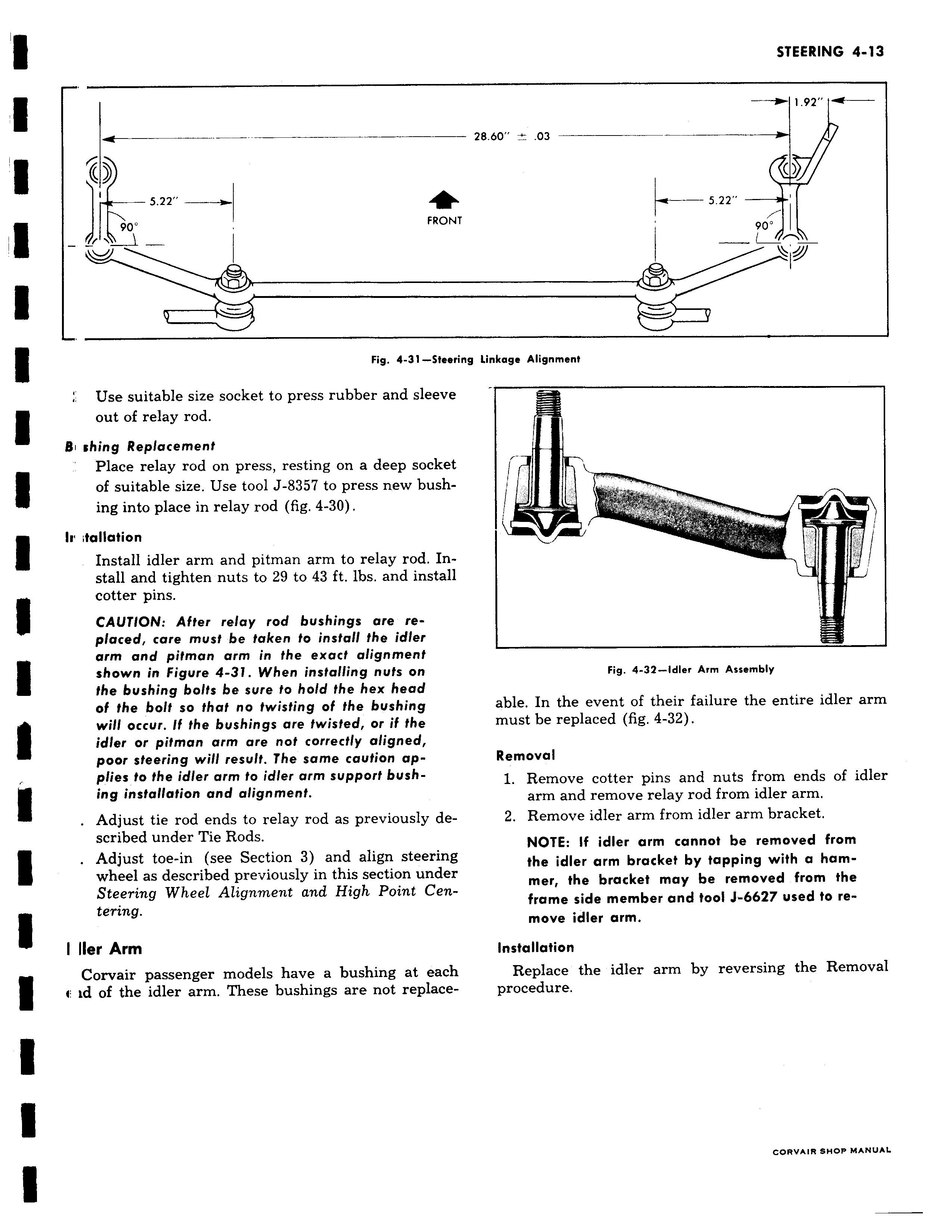
O 5 22 90 FROI Fig 4 31 Stee Use suitable size socket to press rubber and sleevi out of relay rod B rhing Replacement Place relay rod on press resting on a deep socke of suitable size Use tool J 8357 to press new bush ing into place in relay rod fig 4 30 Ir tanaticn Install idler arm and pitman arm to relay rod In stall and tighten nuts to 29 to 43 ft lbs and instal cotter pins CAUTION After relay rod bushings are replaced care must be taken to install the idler arm and pitman arm in the exact alignment shown in Figure 4 31 When installing nuts on the bushing bolts be sure to hold the hex head of the bolt so that no twisting of the bushing will occur If the bushings are twisted or if the idler or pitman arm are not correctly aligned poor steering will result The same caution applies to the idler arm to idler arm support bushing installation and alignment Adjust tie rod ends to relay rod as previously described under Tie Rods Adjust toe in see Section 3 and align steering wheel as described previously in this section undei Steering Wheel Alignment and High Point Centering I Her Arm Corvair passenger models have a bushing at each 4 id of the idler arm These bushings are not replace w 1 92 t 28 60 03 c 5 22 JT 90 ring linkage Alignment I Fig 4 32 Idler Arm Assembly able In the event of their failure the entire idler arm must be replaced fig 4 32 Removal 1 Remove cotter pins and nuts from ends of idler arm and remove relay rod from idler arm 2 Remove idler arm from idler arm bracket NOTE If idler arm cannot be removed from the idler arm bracket by tapping with a ham mer the bracket may be removed from the frame side member and tool J 6627 used to remove idler arm Installation Replace the idler arm by reversing the Removal procedure CORVAIR SHOP MANUAL

 Next
Next