Jeep Parts Wiki | Ford Parts Wiki
Home | Search | Browse
Prev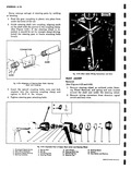
 Next
Next
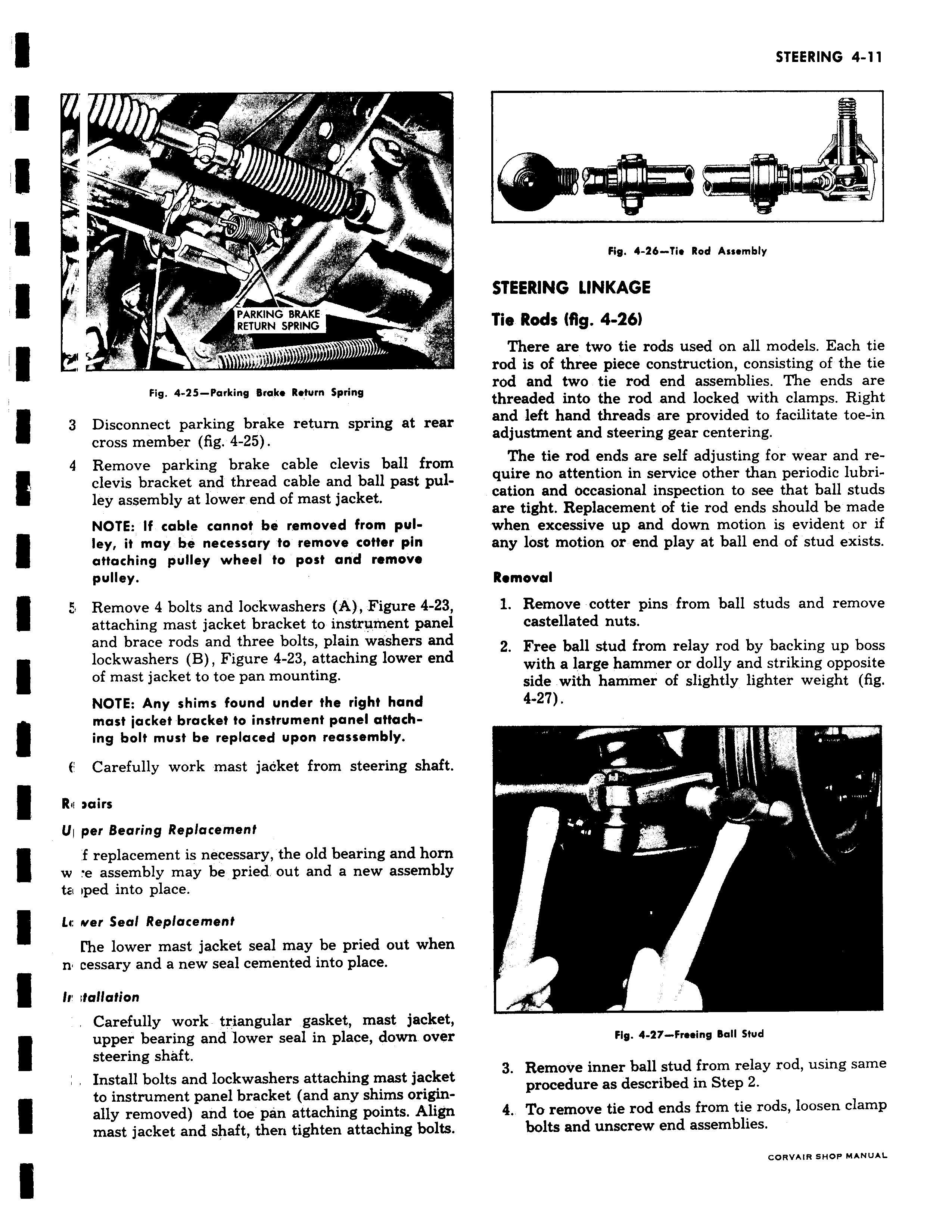
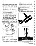
r k PARKING BRAKE RETURN SPRING Fig 4 25 Parking Brake Return Spring 3 Disconnect parking brake return spring at rear cross member fig 4 25 9 Remove parking brake cable clevis ball from clevis bracket and thread cable and ball past pulley assembly at lower end of mast jacket NOTE If cable cannot be removed from pulley it may be necessary to remove cotter pin attaching pulley wheel to post and remove pulley Remove 4 bolts and lockwashers A Figure 4 23 attaching mast jacket bracket to instrument panel and brace rods and three bolts plain washers and lockwashers B Figure 4 23 attaching lower end of mast jacket to toe pan mounting NOTE Any shims found under the right hand most jacket bracket to instrument panel attach ing bolt must be replaced upon reassembly f Carefully work mast jacket from steering shaft R mirs U1 per Bearing Replacement f replacement is necessary the old bearing and horn w e assembly may be pried out and a new assembly ta iped into place Lc over Seal Replacement Me lower mast jacket seal may be pried out when n cessary and a new seal cemented into place In foliation Carefully work triangular gasket mast jacket upper bearing and lower seal in place down over steering shaft Install bolts and lockwashers attaching mast jacket to instrument panel bracket and any shims origin ally removed and toe pan attaching points Align mast jacket and shaft then tighten attaching bolts Fig 4 26 Tie Rod Assembly STEERING LINKAGE Tie Rods fig 4 261 There are two tie rods used on all models Each tie rod is of three piece construction consisting of the tie rod and two tie rod end assemblies The ends are threaded into the rod and locked with clamps Right and left hand threads are provided to facilitate toe in adjustment and steering gear centering The tie rod ends are self adjusting for wear and require no attention in service other than periodic lubrication and occasional inspection to see that ball studs are tight Replacement of tie rod ends should be made when excessive up and down motion is evident or if any lost motion or end play at ball end of stud exists Removal 1 Remove cotter pins from ball studs and remove castellated nuts 2 Free ball stud from relay rod by backing up boss with a large hammer or dolly and striking opposite side with hammer of slightly lighter weight fig 4 27 y Fig 4 27 Freeing Ball Stud 3 Remove inner ball stud from relay rod using same procedure as described in Step 2 4 To remove tie rod ends from tie rods loosen clamp bolts and unscrew end assemblies CORVAIR SHOP MANUAL