Jeep Parts Wiki | Ford Parts Wiki
Home | Search | Browse
Prev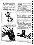

 Next
Next
5673960
5673960
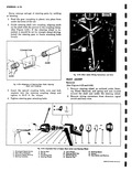
the end of sector shaft Check the end clearance which should not be greater than 002 Fig 4 19 For the purpose of adjusting this end clearance a steering gear lash adjuster shim unit Part Number 5673960 is available It contains four shims 063 065 067 and 069 thick 4 After lash adjuster end clearance has been adjusted start shaft pilot into side cover Then using a screwdriver through the hole in cover turn lash adjuster in a counterclockwise direction to pull sector shaft pilot into side cover as far as it will go 5 Rotate wormshaft by hand until ball nut is about in the center of travel This is to make sure that the rack and sector will engage properly with center tooth of the sector entering center tooth space of the nut 6 Place a new gasket on side cover then push side cover assembly including sector shaft into place After making sure there is some lash between rack and sector teeth assemble and tighten side cover bolts Act ustment on Bench 1 Tighten the worm bearing adjuster until all wormshaft end play has been removed Then tighten the lock nut 2 Using a suitable size socket and a low reading inch lb torque wrench on the worm shaft carefully turn the wormshaft all the way in one direction and then back one turn fig 4 20 Fig 4 20 Checking Worm Bearing Pre load Continue turning the torque wrench noting the torque necessary to keep the shaft in motion This should be between 2 and 6 inch lbs If necessary adjust the worm bearing adjuster until proper pull is obtained v r r rt Fig 4 21 Lash Adjustment 4 Using the torque wrench turn the gear all the way from one stop to the other counting the number of turns Then turn back exactly half that number of turns to the center position 5 Turn the lash adjuster screw clockwise to remove all lash between rack and sector teeth Tighten the lock nut fig 4 21 NOTE Be sure the adjustment is not changed while tightening the locknut 6 Again check the torque wrench while turning the gear through the center position The highest reading in the scale should be between 7 and 12 inch lbs 7 If necessary readjust lash adjuster screw to obtain proper pull Tighten lock nut and again check pull at the worm shaft 8 Fill the assembly with steering gear lubricant to the level of the filler plug hole and replace the filler plug 9 Place the coupling in the proper position on the wormshaft The sawcut in the coupling should line up with the mark on the wormshaft and should be in the 6 o clock position Installation Never substitute bolts of any type regardless of supposed quality for the special bolts designed for use in the steering coupling Consult parts catalog for the order number of these parts when replacement becomes necessary Always clean any foreign material from serrations on worm and steering shaft ends and inside of steering coupling before assembly Battered rusted or corroded parts must be replaced CORVAIR SHOP MANUAL