Jeep Parts Wiki | Ford Parts Wiki
Home | Search | Browse
Prev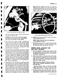
 Next
Next
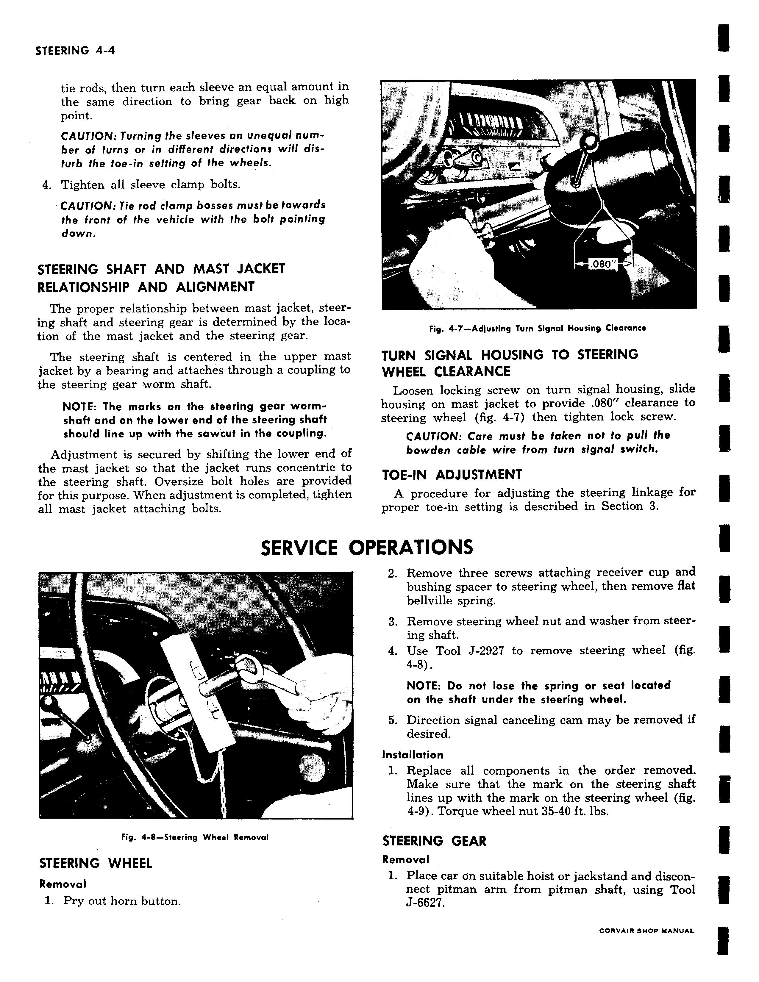
tie rods then turn each sleeve an equal amount in the same direction to bring gear back on high point CAUTION Turning the sleeves an unequal number of turns or in different directions will disturb the toe in setting of the wheels 4 Tighten all sleeve clamp bolts CAUTION Tie rod clamp bosses must be towards the front of the vehicle with the bolt pointing down STEERING SHAFT AND MAST JACKET RELATIONSHIP AND ALIGNMENT The proper relationship between mast jacket steering shaft and steering gear is determined by the location of the mast jacket and the steering gear The steering shaft is centered in the upper mast jacket by a bearing and attaches through a coupling to the steering gear worm shaft NOTE The marks on the steering gear wormshaft and on the lower end of the steering shaft should line up with the sawcut in the coupling Adjustment is secured by shifting the lower end of the mast jacket so that the jacket runs concentric to the steering shaft Oversize bolt holes are provided for this purpose When adjustment is completed tighten all mast jacket attaching bolts SERVICE 0 v Fig 4 8 Steering Wheel Removal STEERING WHEEL Removal 1 Pry out horn button II Fig 4 7 Adjusting Turn Signal Housing Clearance TURN SIGNAL HOUSING TO STEERING WHEEL CLEARANCE Loosen locking screw on turn signal housing slide housing on mast jacket to provide 080 clearance to steering wheel fig 4 7 then tighten lock screw CAUTION Care must be taken not to pull the bowden cable wire from turn signal switch TOE IN ADJUSTMENT A procedure for adjusting the steering linkage for proper toe in setting is described in Section 3 jPERATIONS 2 Remove three screws attaching receiver cup and bushing spacer to steering wheel then remove flat bellville spring 3 Remove steering wheel nut and washer from steering shaft 4 Use Tool J 2927 to remove steering wheel fig 4 8 NOTE Do not lose the spring or seat located on the shaft under the steering wheel 5 Direction signal canceling cam may be removed if desired Installation 1 Replace all components in the order removed Make sure that the mark on the steering shaft lines up with the mark on the steering wheel fig 4 9 Torque wheel nut 35 40 ft lbs STEERING GEAR Removal 1 Place car on suitable hoist or jackstand and disconnect pitman arm from pitman shaft using Tool J 6627