Jeep Parts Wiki | Ford Parts Wiki
Home | Search | Browse
Prev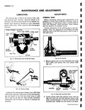
 Next
Next
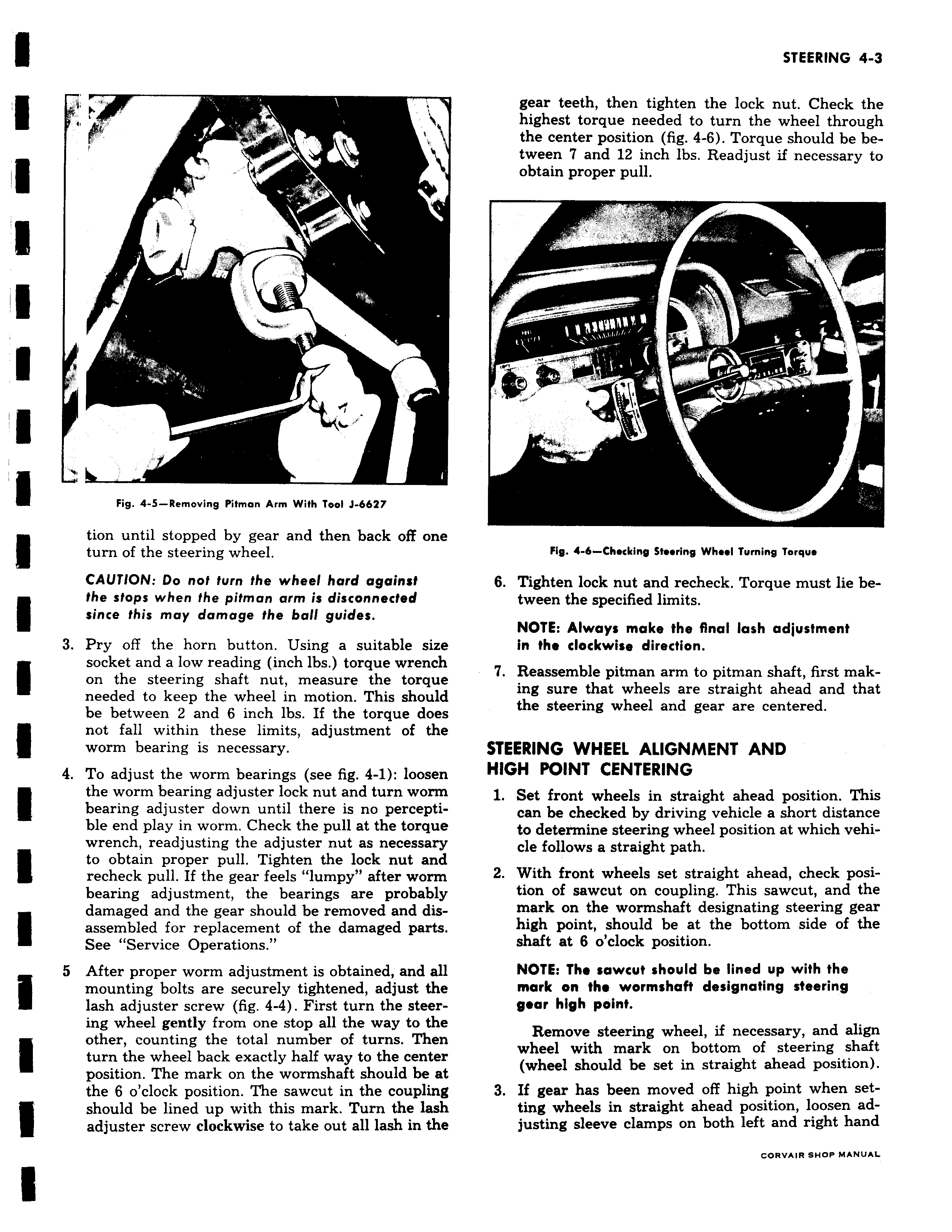
i T y f I r 71 Fig 4 5 Removing Pitman Arm With Tool J 6627 tion until stopped by gear and then back off one turn of the steering wheel CAUTION Do not turn the wheel hard against the stops when the pitman arm is disconnected since this may damage the ball guides 3 Pry off the horn button Using a suitable size socket and a low reading inch lbs torque wrench on the steering shaft nut measure the torque needed to keep the wheel in motion This should be between 2 and 6 inch lbs If the torque does not fall within these limits adjustment of the worm bearing is necessary 4 To adjust the worm bearings see fig 4 1 loosen the worm bearing adjuster lock nut and turn worm bearing adjuster down until there is no percepti ble end play in worm Check the pull at the torque wrench readjusting the adjuster nut as necessary to obtain proper pull Tighten the lock nut and recheck pull If the gear feels lumpy after worm bearing adjustment the bearings are probably damaged and the gear should be removed and disassembled for replacement of the damaged parts See Service Operations 5 After proper worm adjustment is obtained and all mounting bolts are securely tightened adjust the lash adjuster screw fig 4 4 First turn the steering wheel gently from one stop all the way to the other counting the total number of turns Then turn the wheel back exactly half way to the center position The mark on the wormshaft should be at the 6 o clock position The sawcut in the coupling should be lined up with this mark Turn the lash adjuster screw clockwise to take out all lash in the gear teeth then tighten the lock nut Check the highest torque needed to turn the wheel through the center position fig 4 6 Torque should be between 7 and 12 inch lbs Readjust if necessary to obtain proper pull Fig 4 6 Checking Steering Wheel Turning Torque 6 Tighten lock nut and recheck Torque must lie between the specified limits NOTE Always make the final lash adjustment in the clockwise direction 7 Reassemble pitman arm to pitman shaft first making sure that wheels are straight ahead and that the steering wheel and gear are centered STEERING WHEEL ALIGNMENT AND HIGH POINT CENTERING 1 Set front wheels in straight ahead position This can be checked by driving vehicle a short distance to determine steering wheel position at which vehicle follows a straight path 2 With front wheels set straight ahead check position of sawcut on coupling This sawcut and the mark on the wormshaft designating steering gear high point should be at the bottom side of the shaft at 6 o clock position NOTE The sawcut should be lined up with the mark on the wormshaN designating steering gear high point Remove steering wheel if necessary and align wheel with mark on bottom of steering shaft wheel should be set in straight ahead position 3 If gear has been moved off high point when setting wheels in straight ahead position loosen adjusting sleeve clamps on both left and right hand CORVAIR SHOP MANUAL