Jeep Parts Wiki | Ford Parts Wiki
Home | Search | Browse
Prev
 Next
Next
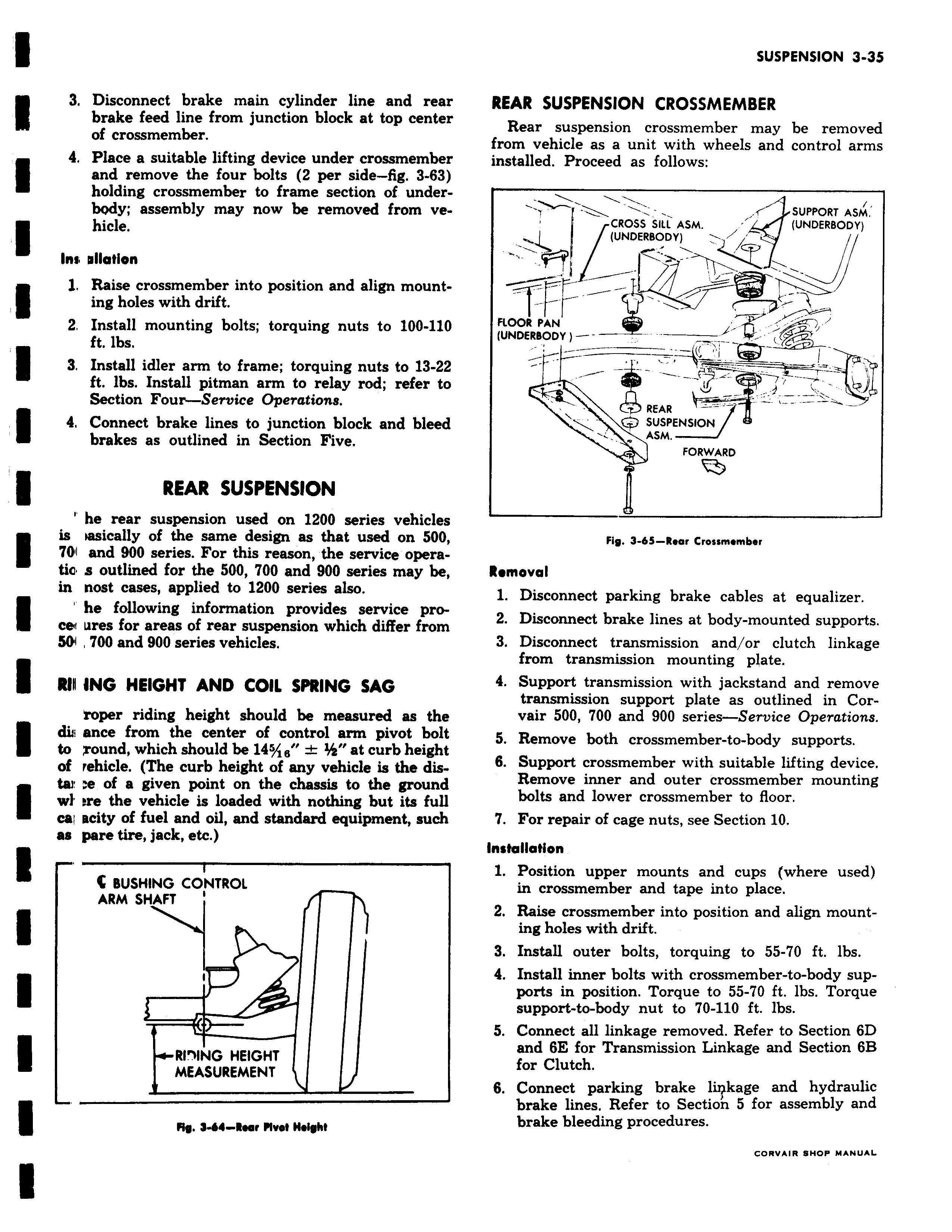
3 Disconnect brake main cylinder line and rear brake feed line from junction block at top center of crossmember 4 Place a suitable lifting device under crossmember and remove the four bolts Z per side fig 3 63 holding crossmember to frame section of underbody assembly may now be removed from vehicle Ins vllarion l Raise crossmember into position and align mount ing holes with drift 2 Install mounting bolts torquing nuts to 100 110 ft lbs 3 Install idler arm to frame torquing nuts to 13 22 ft lbs Install pitman arm to relay rod refer to Section Four Service Operations 4 Connect brake lines to junction block and bleed brakes as outlined in Section Five REAR SUSPENSION he rear suspension used on 1200 series vehicles is iasically of the same design as that used on 500 701 and 900 series For this reason the service operatic s outlined for the 500 700 and 900 series may be in nost cases applied to 1200 series also he following information provides service proce f f ures for areas of rear suspension which differ from SOn 700 and 900 series vehicles RIN ING HEIGHT AND COIL SPRING SAG roper riding height should be measured as the di ance from the center of control arm pivot bolt to round which should be 145 18 at curb height of rehicle The curb height of any vehicle is the distau e of a given point on the chassis to the ground wl ere the vehicle is loaded with nothing but its full cal acity of fuel and oil and standard equipment such as pare tire jack etc BUSHING CONTROL ARM SHAFT i RI ING HEIGHT MEASUREMENT Fig 3 64 Rear rlvel Ileiobt REAR SUSPENSION CROSSMEMBER Rear suspension crossmember may be removed from vehicle as a unit with wheels and control arms installed Proceed as follows w s f SUPPORT ASM CROSS Sill ASM r UNDERBODY UNDERBODY TF FLOOR PAN UNDERBODY REAR SUSPENSION Y ASM FORWARD Fig 3 6S Rear Crossmember Removal 1 Disconnect parking brake cables at equalizer 2 Disconnect brake lines at body mounted supports 3 Disconnect transmission and or clutch linkage from transmission mounting plate 4 Support transmission with jackstand and remove transmission support plate as outlined in Corvair 500 700 and 900 series Service Operations 5 Remove both crossmember to body supports 6 Support crossmember with suitable lifting device Remove inner and outer crossmember mounting bolts and lower crossmember to floor 7 For repair of cage nuts see Section 10 Installation 1 Position upper mounts and cups where used in crossmember and tape into place 2 Raise crossmember into position and align mounting holes with drift 3 Install outer bolts torquing to 55 70 ft lbs 4 Install inner bolts with crossmember to body supports in position Torque to 55 70 ft lbs Torque support to body nut to 70 110 ft lbs 5 Connect all linkage removed Refer to Section 6D and 6E for Transmission Linkage and Section 6B for Clutch 6 Connect parking brake li kage and hydraulic brake lines Refer to Section 5 for assembly and brake bleeding procedures CORVAIR SHOP MANUAL