Jeep Parts Wiki | Ford Parts Wiki
Home | Search | Browse
Prev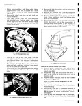
 Next
Next
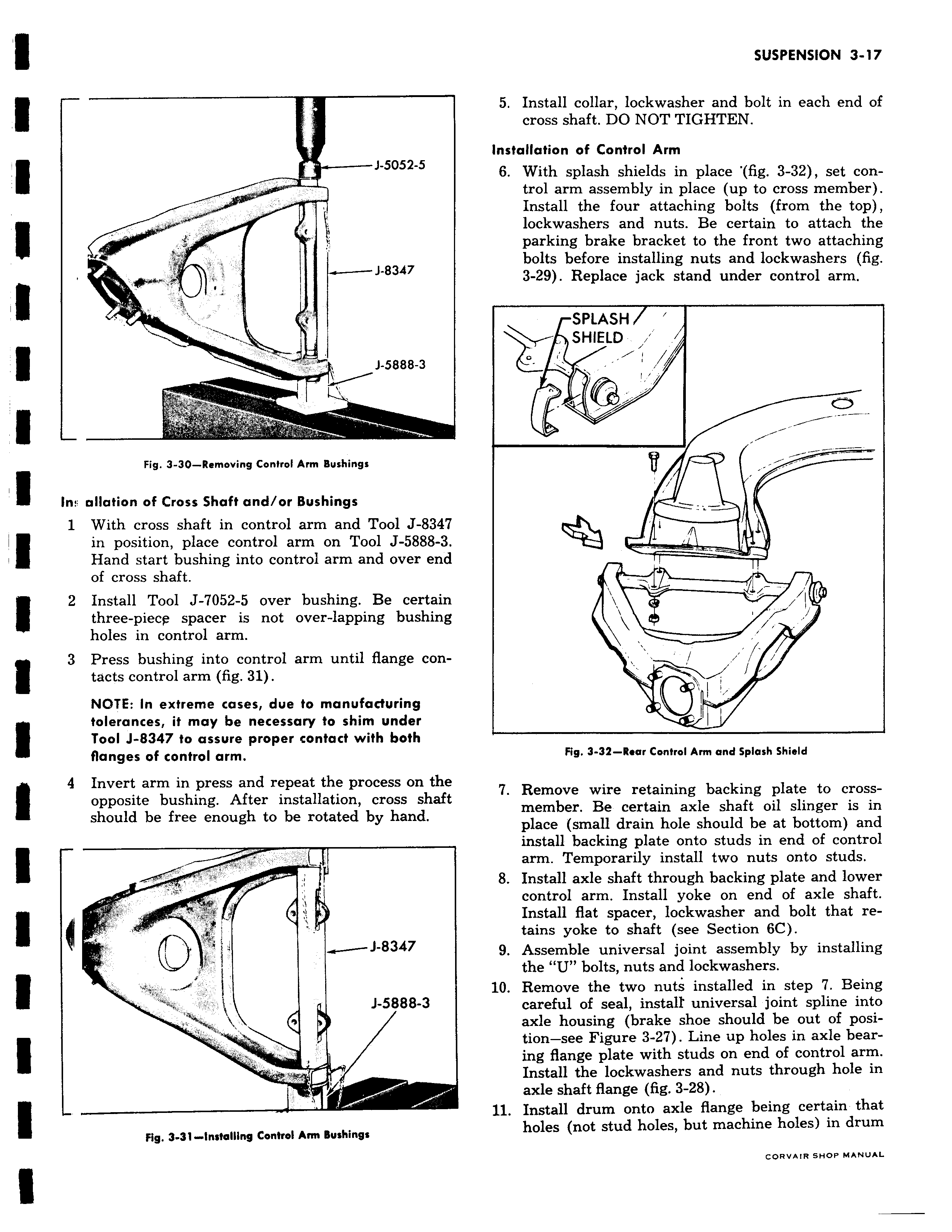
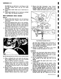
J 5052 5 a J 8347 1 5888 3 p P r Fig 3 30 Removing Control Arm Bushings In ollation of Cross Shaft and or Bushings 1 With cross shaft in control arm and Tool J 8347 in position place control arm on Tool J 5888 3 Hand start bushing into control arm and over end of cross shaft 2 Install Tool J 7052 5 over bushing Be certain three piecp spacer is not over lapping bushing holes in control arm 3 Press bushing into control arm until flange con tacts control arm fig 31 NOTE In extreme cases due to manufacturing I tolerances it may be necessary to shim under Tool J 8347 to assure proper contact with both flanges of control arm r 4 Invert arm in press and repeat the process on the opposite bushing After installation cross shaft should be free enough to be rotated by hand i J 8347 J 5888 3 v Fig 3 31 Installing Control Arm Bushings 5 Install collar lockwasher and bolt in each end of cross shaft DO NOT TIGHTEN Installation of Control Arm 6 With splash shields in place fig 3 32 set control arm assembly in place up to cross member Install the four attaching bolts from the top lockwashers and nuts Be certain to attach the parking brake bracket to the front two attaching bolts before installing nuts and lockwashers fig 3 29 Replace jack stand under control arm SPLASH SHIELD v y I I i Fig 3 32 Rear Control Arm and Splash Shield 7 Remove wire retaining backing plate to crossmember Be certain axle shaft oil slinger is in place small drain hole should be at bottom and install backing plate onto studs in end of control arm Temporarily install two nuts onto studs 8 Install axle shaft through backing plate and lower control arm Install yoke on end of axle shaft Install flat spacer lockwasher and bolt that retains yoke to shaft see Section 6C 9 Assemble universal joint assembly by installing the U bolts nuts and lockwashers 10 Remove the two nuts installed in step 7 Being careful of seal install universal joint spline into axle housing brake shoe should be out of posi tion see Figure 3 27 Line up holes in axle bearing flange plate with studs on end of control arm Install the lockwashers and nuts through hole in axle shaft flange fig 3 28 11 Install drum onto axle flange being certain that holes not stud holes but machine holes in drum CORVAIRSHOP MANUAL