Jeep Parts Wiki | Ford Parts Wiki
Home | Search | Browse
Prev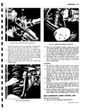
 Next
Next
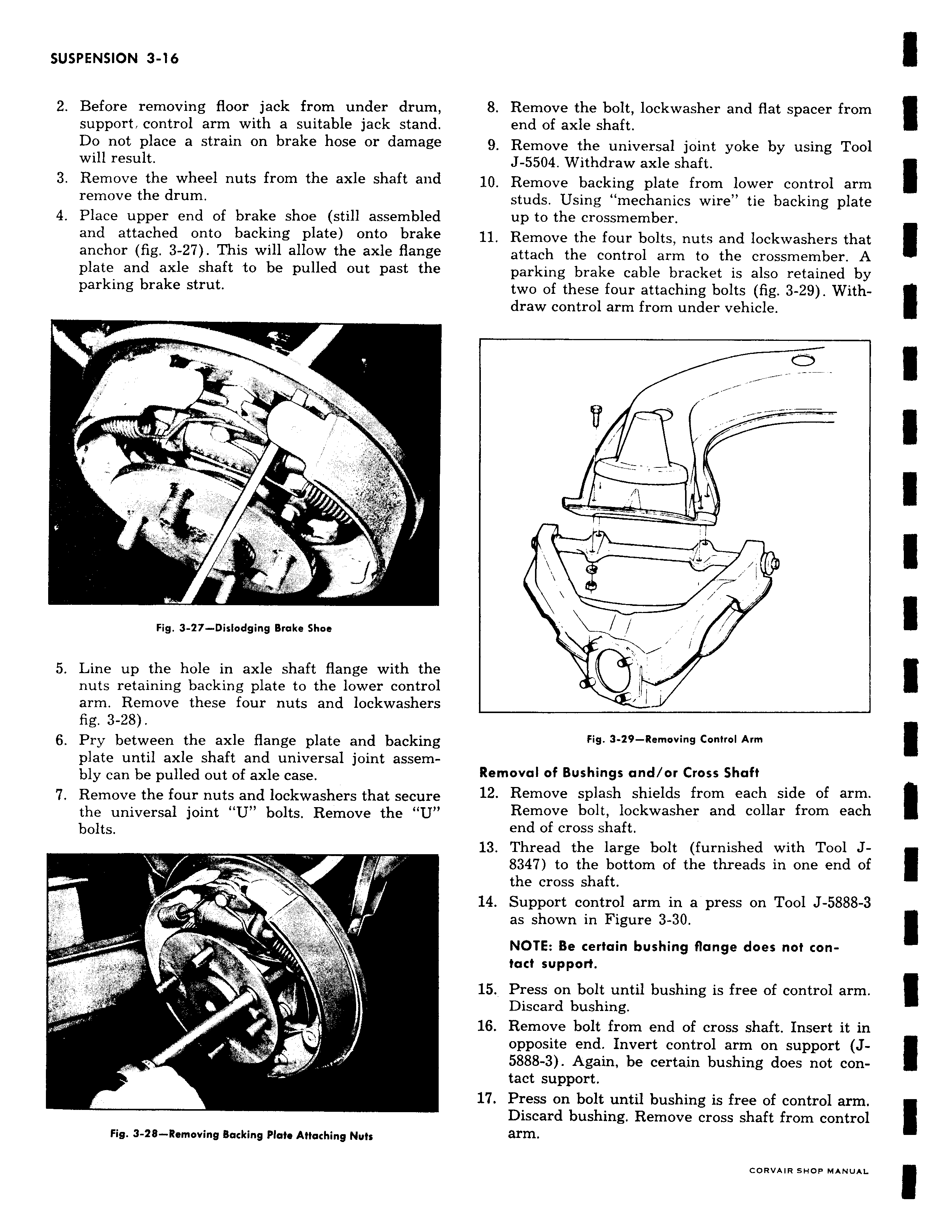
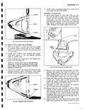
2 Before removing floor jack from under drum support control arm with a suitable jack stand Do not place a strain on brake hose or damage will result 3 Remove the wheel nuts from the axle shaft and remove the drum 4 Place upper end of brake shoe still assembled and attached onto backing plate onto brake anchor fig 3 27 This will allow the axle flange plate and axle shaft to be pulled out past the parking brake strut 4 l W y 1 Fig 3 27 Dislodging Brake Shoe 5 Line up the hole in axle shaft flange with the nuts retaining backing plate to the lower control arm Remove these four nuts and lockwashers fig 3 28 6 Pry between the axle flange plate and backing plate until axle shaft and universal joint assembly can be pulled out of axle case 7 Remove the four nuts and lockwashers that secure the universal joint U bolts Remove the U bolts t 1 lti J rv 1 r y 21 Fig 3 28 Removing Backing Plate Attaching Nuts 8 Remove the bolt lockwasher and flat spacer from end of axle shaft 9 Remove the universal joint yoke by using Tool J 5504 Withdraw axle shaft 10 Remove backing plate from lower control arm studs Using mechanics wire tie backing plate up to the crossmember 11 Remove the four bolts nuts and lockwashers that attach the control arm to the crossmember A parking brake cable bracket is also retained by two of these four attaching bolts fig 3 29 Withdraw control arm from under vehicle j J LX Fig 3 29 Removing Control Arm Removal of Bushings and or Cross Shaft 12 Remove splash shields from each side of arm Remove bolt lockwasher and collar from each end of cross shaft 13 Thread the large bolt furnished with Tool J8347 to the bottom of the threads in one end of the cross shaft 14 Support control arm in a press on Tool J 5888 3 as shown in Figure 3 30 NOTE Be certain bushing flange does not contact support 15 Press on bolt until bushing is free of control arm Discard bushing 16 Remove bolt from end of cross shaft Insert it in opposite end Invert control arm on support J5888 3 Again be certain bushing does not contact support 17 Press on bolt until bushing is free of control arm Discard bushing Remove cross shaft from control arm