Jeep Parts Wiki | Ford Parts Wiki
Home | Search | Browse | Marketplace | Messages | FAQ | Guest
Prev
 Next
Next
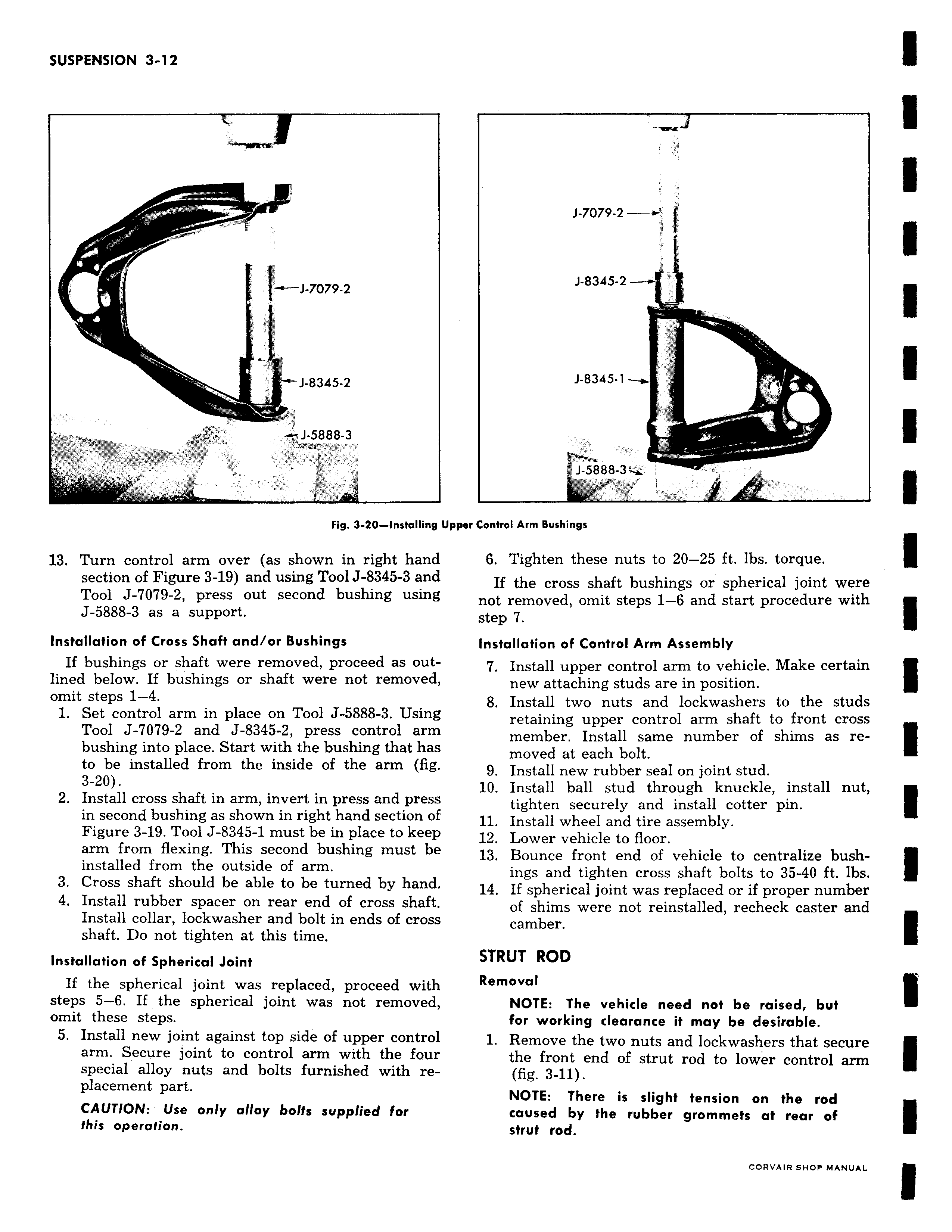
i f J 7079 2 J 8345 2 J 5888 3 Fig 3 20 Installing Up 13 Turn control arm over as shown in right hand section of Figure 3 19 and using Tool J 8345 3 and Tool J 7079 2 press out second bushing using J 5888 3 as a support Installation of Cross Shaft and or Bushings If bushings or shaft were removed proceed as outlined below If bushings or shaft were not removed omit steps 1 4 1 Set control arm in place on Tool J 588 3 Using Tool J 7079 2 and J 8345 2 press control arm bushing into place Start with the bushing that has to be installed from the inside of the arm fig 3 20 2 Install cross shaft in arm invert in press and press in second bushing as shown in right hand section of Figure 3 19 Tool J 8345 1 must be in place to keep arm from flexing This second bushing must be installed from the outside of arm 3 Cross shaft should be able to be turned by hand 4 Install rubber spacer on rear end of cross shaft Install collar lockwasher and bolt in ends of cross shaft Do not tighten at this time Installation of Spherical Joint If the spherical joint was replaced proceed with steps 5 6 If the spherical joint was not removed omit these steps 5 Install new joint against top side of upper control arm Secure joint to control arm with the four special alloy nuts and bolts furnished with replacement part CAUTION Use only alloy bolts supplied for this operation J 7079 2 1 J 8345 2 J 8345 1 J 5888 3y i per Control Arm Bushings 6 Tighten these nuts to 20 25 ft lbs torque If the cross shaft bushings or spherical joint were not removed omit steps 1 6 and start procedure with step 7 Installation of Control Arm Assembly 7 Install upper control arm to vehicle Make certain new attaching studs are in position 8 Install two nuts and lockwashers to the studs retaining upper control arm shaft to front cross member Install same number of shims as removed at each bolt 9 Install new rubber seal on joint stud 10 Install ball stud through knuckle install nut tighten securely and install cotter pin 11 Install wheel and tire assembly 12 Lower vehicle to floor 13 Bounce front end of vehicle to centralize bushings and tighten cross shaft bolts to 35 40 ft lbs 14 If spherical joint was replaced or if proper number of shims were not reinstalled recheck caster and camber STRUT ROD Removal NOTE The vehicle need not be raised but for working clearance it may be desirable 1 Remove the two nuts and lockwashers that secure the front end of strut rod to lower control arm fig 3 11 NOTE There is slight tension on the rod caused by the rubber grommets at rear of strut rod