Jeep Parts Wiki | Ford Parts Wiki
Home | Search | Browse | Marketplace | Messages | FAQ | Guest
Prev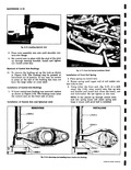
 Next
Next
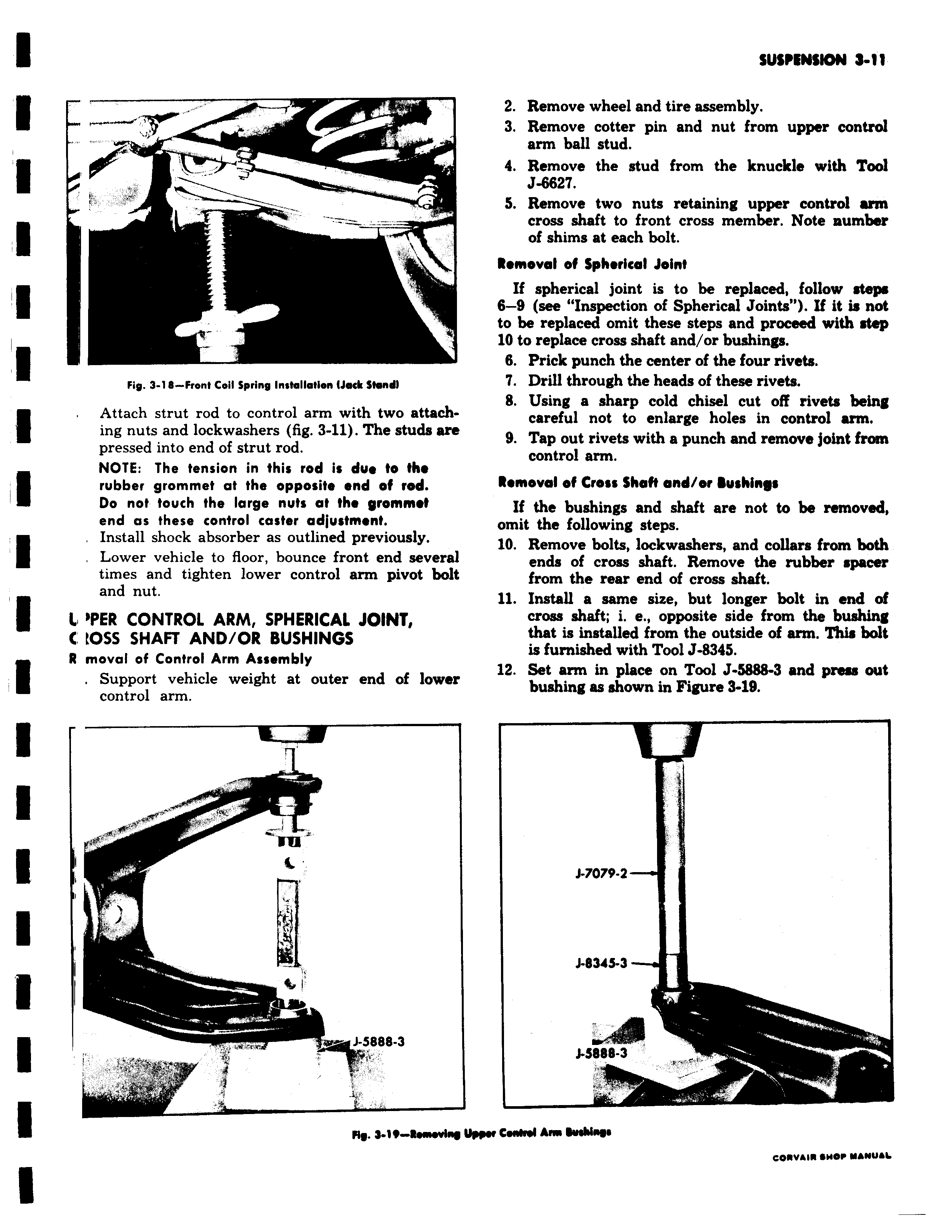
e a v 1 8 Front Coil Spring Installation Jecic Stand Fip 3 Attach strut rod to control arm with two attach ing nuts and lockwashers fig 3 11 The studs ar pressed into end of strut rod NOTE The tension in this rod i due to the rubber grommet at the opposite end of rod Do not touch the large nuts at the grommet end as these control caster adjustment Install shock absorber as outlined previously Lower vehicle to floor bounce front end severs times and tighten lower control arm pivot bol and nut l OPER CONTROL ARM SPHERICAL JOINT C t055 SHAFT AND OR BUSHINGS R moval of Control Arm Assembly Support vehicle weight at outer end of lowe control arm I i J 5888 3 N 1 Rhnwin 2 Remove wheel and tire assembly 3 Remove cotter pin and nut from upper control arm ball stud 4 Remove the stud from the knuckle with Tool J 6627 5 Remove two nuts retaining upper control arm cross shaft to front cross member Note number of shims at each bolt Removal of Spherical Joint If spherical joint is to be replaced follow steps 6 8 see Inspection of Spherical Joints If it is not to be replaced omit these steps and proceed with step 10 to replace cross shaft and or bushings 6 Prick punch the center of the four rivets 7 Drill through the heads of these rivets 8 Using a sharp cold chisel cut off rivets being careful not to enlarge holes in control arm 9 Tap out rivets with a punch and remove joint from control arm Removal of Cross Shaft and or Bushings If the bushings and shaft are not to be removed omit the following steps 10 Remove bolts lockwashers and collars from both ends of cross shaft Remove the rubber spacer t from the rear end of cross shaft 11 Install a same size but longer bolt in end of cross shaft i e opposite side from the bushing that is installed from the outside of arm This bolt is furnished with Tool J 8345 12 Set arm in place on Tool J 5888 3 and press out bushing as shown in Figure 3 19 J 7079 2 J 834S 3 J S888 3 1 Ypw CieMl Am Wddw e COf1VAIR 110 Y NY L