Jeep Parts Wiki | Ford Parts Wiki
Home | Search | Browse | Marketplace | Messages | FAQ | Guest
|
Corvair Assembly Manual December 1964 |
|
Prev
 Next
Next
3862100
3862100
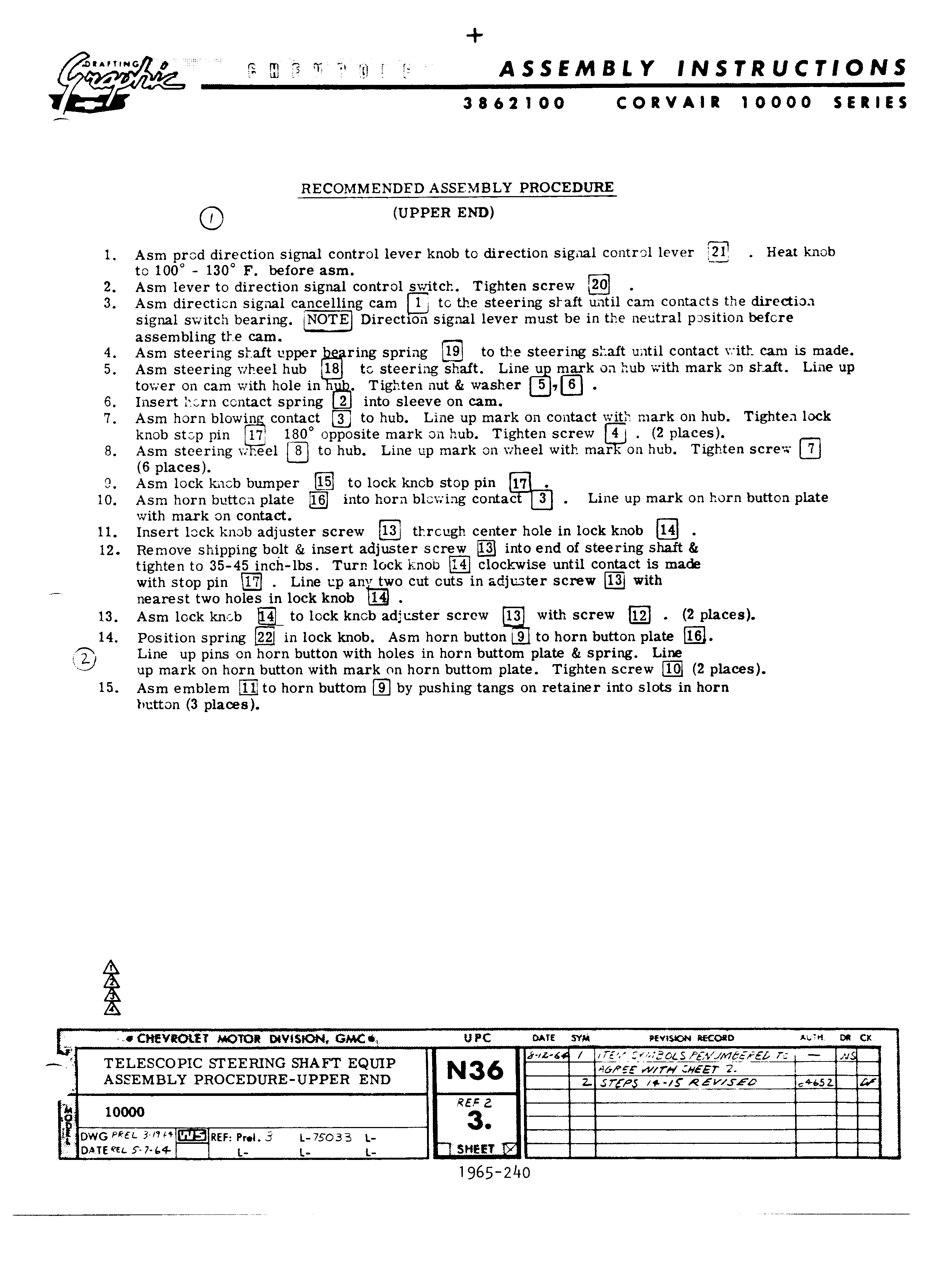
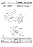
I 0 isi ir ASSEMBLY INSTRUCTIONS 3862100 CORVAIR 10000 SERIES RECOMMENDED ASSEMBLY PROCEDURE Q UPPER END 1 Asm prod direction signal control lever knob to direction signal control lever Heat knob to 100 130 F before asm 2 Asm lever to direction signal control switch Tighten screw QE 3 Asm direction signal cancelling cam to the steering shaft until cam contacts the direction signal switch bearing NOTE Direction signal lever must be in the neutral position before assembling the cam 4 Asm steering shaft upper ring spring 19 to the steering shaft until contact with cam is made 5 Asm steering wheel hub 18 to steering shaft Line u mark on hub with mark on shaft Line up tower on cam with hole in Tighten nut washer 6 Insert horn contact spring into sleeve on cam 7 Asm horn blowin contact Q to hub Line up mark on contact with mark on hub Tighten lock knob stop pin 1a0 opposite mark on hub Tighten screw EJ 2 places 8 Asm steering w eel n to hub Line up mark on wheel with mar on hub Tighten screw 7 6 places 9 Asm lock knob bumper E to lock knob stop pin 17 10 Asm horn button plate 16 into horn blowing contac B Line up mark on horn button plate with mark on contact 11 Insert lock knob adjuster screw 13 through center hole in lock knob 14 12 Remove shipping bolt insert adjuster screw 13 into end of steering shaft tighten to 35 45 inch lbs Turn lock knob 14 clockwise until contact is made with stop pin 17 Line up anv two cut outs in adjuster screw E with M nearest two holes in lock knob 13 Asm lock knob EL to lock knob adjuster screw 13 with screw 12 2 places 14 Position spring il in lock knob Asm horn button 9 to horn button plate 16 Line up pins on horn button with holes in horn buttom plate spring Line up mark on horn button with mark on horn buttom plate Tighten screw 10 2 places 15 Asm emblem to horn buttom E by pushing tangs on retainer into slots in horn button 3 places Q CH VRO E MOTOR DQWSION GMCQ UPC A E svn revision necoeo i i on cx TELESCOPIC STEERING SHAFT EQUIP L f if 75 ASSEMBLY PROCEDURE UPPER END Q 2 7 4 e v 0 4 5 REF Z 1 10000 3 fi DWG We 3 Rtr P 1 75022 t r r TE f 7 Q t 1 1 I SHPFT Ki 1965 2i O