Jeep Parts Wiki | Ford Parts Wiki
Home | Search | Browse
|
Corvair Chassis Shop Manual December 1964 |
|
Prev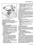
 Next
Next
The following procedure is presented as a guide for us when inspecting a damaged vehicle equipped with air conditioning 1 Remove the drive belt Cut belt off if necessary 2 Visually inspect the condenser receiver dehydrator compressor mounting brackets conditioning unit all connecting lines and all controls to determine the extent and nature of the damage a No repairs such as soldering welding or brazing should be attempted on the condenser be cause of its construction If the vapor passages in the horizontal tubes or return bends or manifolds have been damaged in any way the condenser should be replaced with a new one b The receiver dehydrator should be replaced if there is any evidence of its having sustained either internal damage or a fracture at any of the lines or welded joints or if the system has been exposed to the atmosphere for an undetermined period of time c Examine the compressor for any visible external damage d The evaporator should be examined for damage and if necessary removed or replaced or the entire unit processed where damaged or expoSe to the atmosphere e All connecting lines and flexible hoses should b examined throughout their entire length for damage If damaged in any manner replace with new lines f Check all controls and connecting wires for damage and replace with new parts where needed g Check the clutch pulley for proper operation and freedom from damage 3 Install gauge set 4 Purge the system Pressure should not exceed 3ta 5 pounds 5 Remove the compressor from mounting and remove the oil test fitting 6 Four out the oil into a clean glass container an examine it for any foreign substance such as dirt water metal particles etc If any of these are pre sent the compressor and receiver dehydrator should be replaced and the other system components should be flushed with liquid refrigerant 7 If the oil is clean and free of any harmful substance l replace oil with Frigidaire Oil available through Parts Stock NOTE If the system components have been replaced or flushed replace the full charge of oil If not add no more fresh oil than was drained in Step 6 8 Charge up the compressor to drum or can pressure and leak test the compressor seals prior to installa tion of compressor Use a special cover plate that can be fabricated as described under I Compressor Seal Replacement Installation Step 10 9 Reinstall the compressor and evacuate the system by following the Evacuating Procedure 10 Introduce R 12 vapor at cylinder room temperature and pressure i 11 Leak test all fittings and connections and give par I ticular attention to a leak test at the compressorl shaft seal if compressor has not been leak tested on the bench 12 Coxnplete system processing and charge system FLUSHING THE SYSTEM To flush the components of the system with liquid refrigerant connect the refrigerant can or drum to the unit bei flushed turn the can or drum upside down and open the can or drum valve Remove the refrigerant lines and flush all components separately Do not attempt to flush the entire system without first separating the components CAUTION As liquid R 12 enters an area of atmpspheric pressure its temperature will immediately drop to 21 7 F Be sure to direct the outlet of the unit or units being flushed into an areA where the extreme cold of the escaping refrigerant will do no harm Dry nitrogen may also be used to flush the system components Drum pressure should not exceed 125 psi FAST IDLE ADJUSTMENT The Qorvair Air Conditioning System requires an engine idle speed of 550 rpm for proper operation With refrigeration system on and selector in drive automatic or gearshift in neutral manual adjust the idle screw until an engine speed of 550 rpm is attained fig 58 Also a head pressure of 300 psi should be indicated for the refrigeration system NOTE If head pressure is lower than 300 psi at idle the engine will stall when higher pressures are attained under actual operating conditions OPERATING INSTRUCTIONS The Corvair air conditioner a fresh air type has three control levers and fan switch to provide control of cool air flow A fourth lever controls heater temperature optput The air flow can be directed through the two fromit ball outlets and the center outlet bezel Always operate the Air Conditioning System with all windows and vents closed to eliminate drafts wind and road noise Cover plate furnished should remain installed over the engine air recirculating slot during the season when cooling is required This plate should be removed and atorved on top of the rear sill for the winter See Figure 59 AIR CONDITIONING CONTROL PANEL The 1965 Corvair Air Conditioning control panel makes use of four vertical acting levers and a single fan switch Control operation is as follows HEAT DEFROST These two levers serve the same purpose as the regular production direct air heater controls For their operation see the heater in formation contained earlier in this section AIR For maximum cooling capacity during periods of extreme heat and humidity and when first turning on the system the AIR lever should be in the full up position to supply full re circulated air to the system The lever may be depressed a short distance to supply some