Jeep Parts Wiki | Ford Parts Wiki
Home | Search | Browse
|
Corvair Chassis Shop Manual December 1964 |
|
Prev
 Next
Next
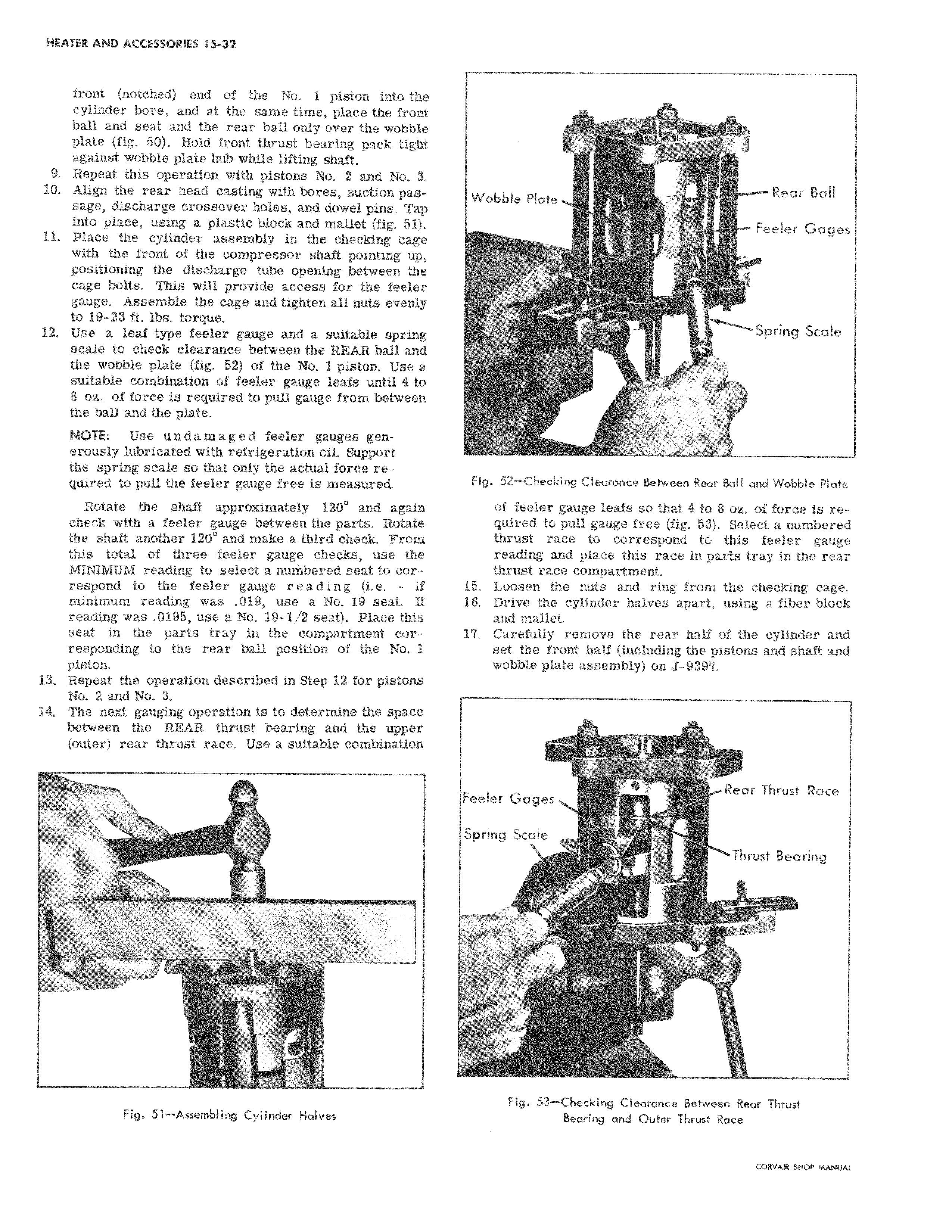
front notched end of the No 1 piston into the cylinder bore and at the same time place the fron ball and seat and the rear ball only over the wobble plate fig 50 Hold front thrust bearing pack tight against wobble plate hub while lifting shaft 9 Repeat this operation with pistons No 2 and No 31 10 Align the rear head casting with bores suction pas 4 sage discharge crossover holes and dowel pins Tap into place using a plastic block and mallet fig 51 11 Place the cylinder assembly in the checking cage with the front of the compressor shaft pointing up positioning the discharge tube opening between the cage bolts This will provide access for the feeler gauge Assemble the cage and tighten all nuts evenly to 19 23 ft lbs torque 12 Use a leaf type feeler gauge and a suitable spring scale to check clearance between the REAR ball and the wobble plate fig 52 of the No 1 piston Use aj suitable combination of feeler gauge leafs until 4 t S oz of force is required to pull gauge from between the ball and the plate NOTE Use undamaged feeler gauges generously lubricated with refrigeration oil Support the spring scale so that only the actual force required to pull the feeler gauge free is measured i Rotate the shaft approximately 120 and againl check with a feeler gauge between the parts Rotate the shaft another 120 and make a third check From this total of three feeler gauge checks use the MINIMUM reading to select a numbered seat to correspond to the feeler gauge r e a d i n g i e if minimum reading was 019 use a No 19 seat 1f reading was 0195 use a No 19 1 2 seat Place this seat in the parts tray in the compartment corresponding to the rear ball position of the No 1 piston 13 Repeat the operation described in Step 12 for pistons j No 2 and No 3 14 The next gauging operation is to determine the space between the REAR thrust bearing and the upper outer rear thrust race Use a suitable combination Fig 52 Checking Clearance Between Rear Ball and Wobble Plate of fleler gauge leafs so that 4 to 8 oz of force is requiried to pull gauge free fig 53 Select a numbered thrust race to correspond to this feeler gauge reading and place this race in parts tray in the rear thrust race compartment 15 Loosen the nuts and ring from the checking cage 16 Drive the cylinder halves apart using a fiber block and mallet 17 Carefully remove the rear half of the cylinder and set the from half including the pistons and shaft and wobble plate assembly on J 9397