Jeep Parts Wiki | Ford Parts Wiki
Home | Search | Browse
|
Corvair Chassis Shop Manual December 1964 |
|
Prev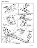
 Next
Next
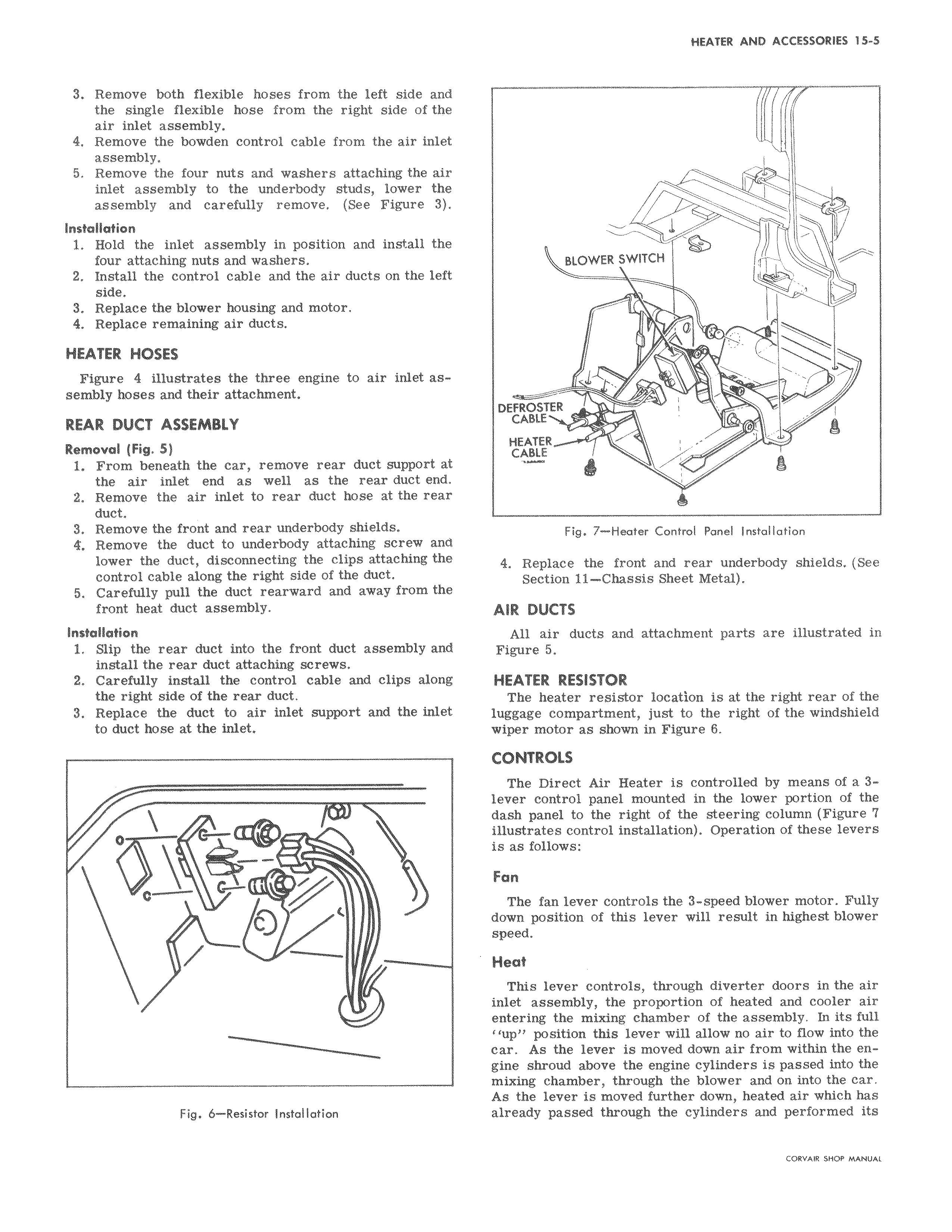
3 Remove both flexible hoses from the left side and the single flexible hose from the right side of the air inlet assembly 4 Remove the bowden control cable from the air inlet assembly 5 Remove the four nuts and washers attaching the air inlet assembly to the underbody studs lower the assembly and carefully remove See Figure 3 Installation 1 Hold the inlet assembly in position and install the four attaching nuts and washers 2 Install the control cable and the air ducts on the left side 3 Replace the blower housing and motor 4 Replace remaining air ducts HEATER HOSES Figure 4 illustrates the three engine to air inlet assembly hoses and their attachment REAR DUCT ASSEMBLY Removal Fig S 1 From beneath the car remove rear duct support at the air inlet end as well as the rear duct end 2 Remove the air inlet to rear duct hose at the rear duct 3 Remove the front and rear underbody shields 4 Remove the duct to underbody attaching screw and lower the duct disconnecting the clips attaching the control cable along the right side of the duct 5 Carefully pull the duct rearward and away from the front heat duct assembly Installation 1 Slip the rear duct into the front duct assembly and install the rear duct attaching screws 2 Carefully install the control cable and clips along the right side of the rear duct 3 Replace the duct to air inlet support and the inlet to duct hose at the inlet O Fig 6 Resistor Installation BLOWER SWITCH v i DEFROSTER R C HEATER CABLE V Fig 7 Heater Control Panel Installation 4 Replace the front and rear underbody shields See Section 11 Chassis Sheet Metal AIR DUCTS All air ducts and attachment parts are illustrated in Figure 5 HEATER RESISTOR The heater resistor location is at the right rear of the luggage compartment just to the right of the windshield wiper motor as shown in Figure 6 CONTROLS The Direct Air Heater is controlled by means of a 3lever control panel mounted in the lower portion of the dash panel to the right of the steering column Figure 7 illustrates control installation Operation of these levers is as follows Fan The fan lever controls the 3 speed blower motor Fully down position of this lever will result in highest blower speed Heat This lever controls through diverter doors in the air inlet assembly the proportion of heated and cooler air entering the mixing chamber of the assembly In its full up position this lever will allow no air to flow into the car As the lever is moved down air from within the engine shroud above the engine cylinders is passed into the mixing chamber through the blower and on into the car As the lever is moved further down heated air which has already passed through the cylinders and performed its CORVAit HOP MANUAL