Jeep Parts Wiki | Ford Parts Wiki
Home | Search | Browse | Marketplace | Messages | FAQ | Guest
|
Corvair Chassis Shop Manual December 1964 |
|
Prev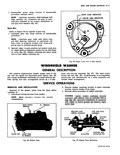
 Next
Next
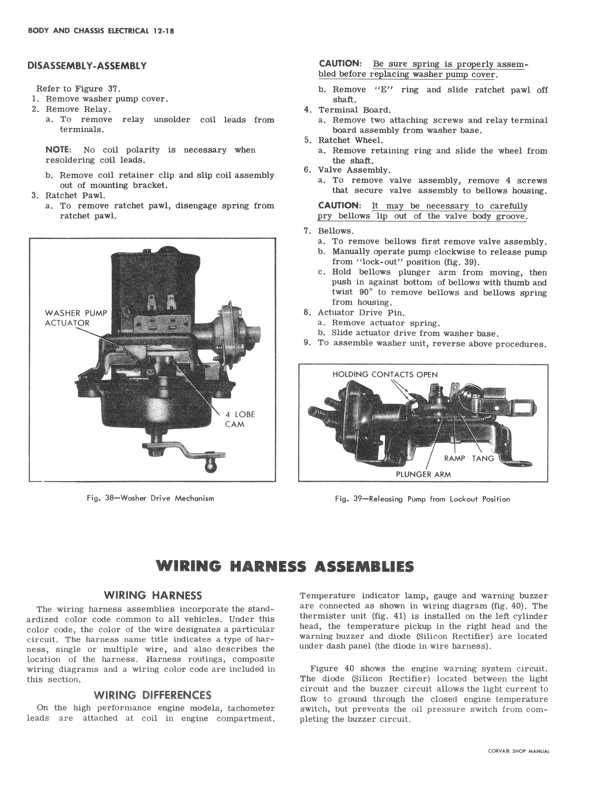
DISASSEMBLY ASSEMBLY Refer to Figure 37 1 Remove washer pump cover 2 Remove Relay a To remove relay unsolder coil leads from terminals i NOTE No coil polarity is necessary when resoldering coil leads b Remove coil retainer clip and slip coil assembl out of mounting bracket 3 Ratchet Pawl a To remove ratchet pawl disengage spring from ratchet pawl WASHER PUMP ACTUATOR R 4 LOBE CAM Fig 38 Washer Drive Mechanism WIRING FIARNE WIRING HARNESS The wiring harness assemblies incorporate the stand ardized color code common to all vehicles Under Id color code the color of the wire designates a particular circuit The harness name title indicates a type of harness single or multiple wire and also describes the location of the harness Harness routings composite wiring diagrams and a wiring color code are included i this section WIRING DIFFERENCES On the high performance engine models tachomete leads are attached at coil in engine compartment CAUTION Be sure spring is properly assembled before replacing washer pump cover b Remove E ring and slide ratchet pawl off haft 4 Terminal Hoard a Remove two attaching screws and relay terminal board assembly from washer base 5 Ratchet Wheel a Remove retaining ring and slide the wheel from the shaft 8 Valve Assembly a To remove valve assembly remove 4 screws that secure valve assembly to bellows housing CAtriION It may be necessary to carefully pry bellows lip out of the valve body groove 7 Bellows a To remove bellows first remove valve assembly b Manually operate pump clockwise to release pump from lock out position fig 39 c told bellows plunger arm from moving then push in against bottom of bellows with thumb and twist 90 to remove bellows and bellows spring from housing 8 Actuator Drive Pin a Remove actuator spring b Slide actuator drive from washer base 9 To akssemble washer unit reverse above procedures HOLDING CONTACTS OPEN RAMP TANG PLUNGER ARM Fig 39 Releasing Pump from Lockout Position i5 ASSEMBLIES Temperature indicator lamp gauge and warning buzzer are conilected as shown in wiring diagram fig 40 The thermisder unit fig 41 is installed on the left cylinder head the temperature pickup in the right head and the warning zzer and diode Silicon Rectifier are located under daYsh panel the diode in wire harness Figure 40 shows the engine warning system circuit The diode Silicon Rectifier located between the light circuit and the buzzer circuit allows the light current to flow to ground through the closed engine temperature switch but prevents the oil pressure switch from completing the buzzer circuit