Jeep Parts Wiki | Ford Parts Wiki
Home | Search | Browse | Marketplace | Messages | FAQ | Guest
|
Corvair Chassis Shop Manual December 1964 |
|
Prev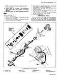
 Next
Next
The directional signal control is one complete plastid assembly using a stamped bowl instead of an integral cast bowl The bowl serves only as a housing ADJUSTMENTS The directional signal mechanism requires no adjustments due to its simplicity of design However if any malfunction of this mechanism should occur the steering wheel may be removed and the mechanism checked for defective parts REMOVAL AND INSTALLATION Fig 28 Standard Models 1 Disconnect battery ground cable 2 Remove steering wheel assembly Refer to Section 9 Steering 3 Disconnect signal control wiring assembly at harness quick disconnect 4 Remove steering column mast jacket upper support clamp 5 Remove directional signal lever and three screws attaching control assembly to the retaining plate 6 Remove directional signAl control assembly retaining plate and signal housing from steering column dis engage wiring from housing 7 To install reverse removal procedures CAUTION Direction signal control assembly must be in neutral position when assembling steering wheel to prevent damage to cancelling cam and control assembly Telescoping Steering Wheel Fig 28 Removal 1 Disconnect battery ground cable 2 Remove steering wheel and hub assembly as outlined in Section 9 Steering WINDSNIEI GENERAL DE The regular production single speed electric windshield wiper assembly available on the 1965 Corvair incorporates a non depressed type blades park approximately 2 above windshield molding motor and gear train The rectangular 12 volt shunt wound motor i coupled to a gear train consisting of a helical drive gea at the end of the motor armature shaft an intermediat gear and pinion assembly and an output gear and s assembly The crank arm is attached to the output gea shaft SERVICE IOF WIPER TRANSMISSION ASSEMBLY REMOVAL AND INSTALLATION Fig 29 1 Make certain motor is in park position remove wiper arm and blade assemblies from transmission shaft 2 Remove plenum chamber grille 3 Remove spring and cancelling cam from steering shaft 4 Remove turn signal lever retaining screw and lever 5 Remove the three screws retaining directional control to the retaining plate 6 Remove wiring clamp and cover from directional signal wiring harness 7 Remove the wire terminals from the plastic connectors using a small thin bladed screw driver NOTE To facilitate reassembly record the color code of the wires 8 Guiding the wiring carefully pull the directional signal switch out of the housing Installation 1 Position directional signal switch into housing being careful to properly route wiring through guide in housing 2 Install retaining plate and control retaining screws 3 Install direction signal wiring cover over harness and slide it up into place in the housing guides 4 Engage wiring clamp tang in mast jacket hole and secure with retaining screw 5 Install wiring terminals into plastic connectors and connect to body wiring harness 6 Position directional signal lever and install retaining screw 7 Place cancelling cam and spring into position on steering shaft CAUTION Direction signal control assembly must be in neutral position when assembling steering wheel to prevent damage to cancelling cam and control assembly 8 Install steering wheel and hub assembly as outlined in Section 9 Steering 9 Connect battery ground cable and check operation of unit D WIPER SCRIPTION h The bptionally available two speed non depressed wiper and washer assembly incorporates a rectangular compound wound series and shunt field motor adapted to the same type gear train as that used with the new single speed wipers Two switches connected in parallel control the starting stopping an parking of both types of wiper motors The manually operated start stop switch is located on the dash panel while the cam operated park switch is located in the wiper gear box ERATIONS Loosen nuts retaining drive link to crank arm ball joint and disconnect drive link from crank arm View B fig 29 4 Remove transmission retaining screws lower assembly into plenum chamber and remove complete unit from the chamber 5 To install reverse removal procedure and check operation of unit