Jeep Parts Wiki | Ford Parts Wiki
Home | Search | Browse | Marketplace | Messages | FAQ | Guest
|
Corvair Chassis Shop Manual December 1964 |
|
Prev
 Next
Next
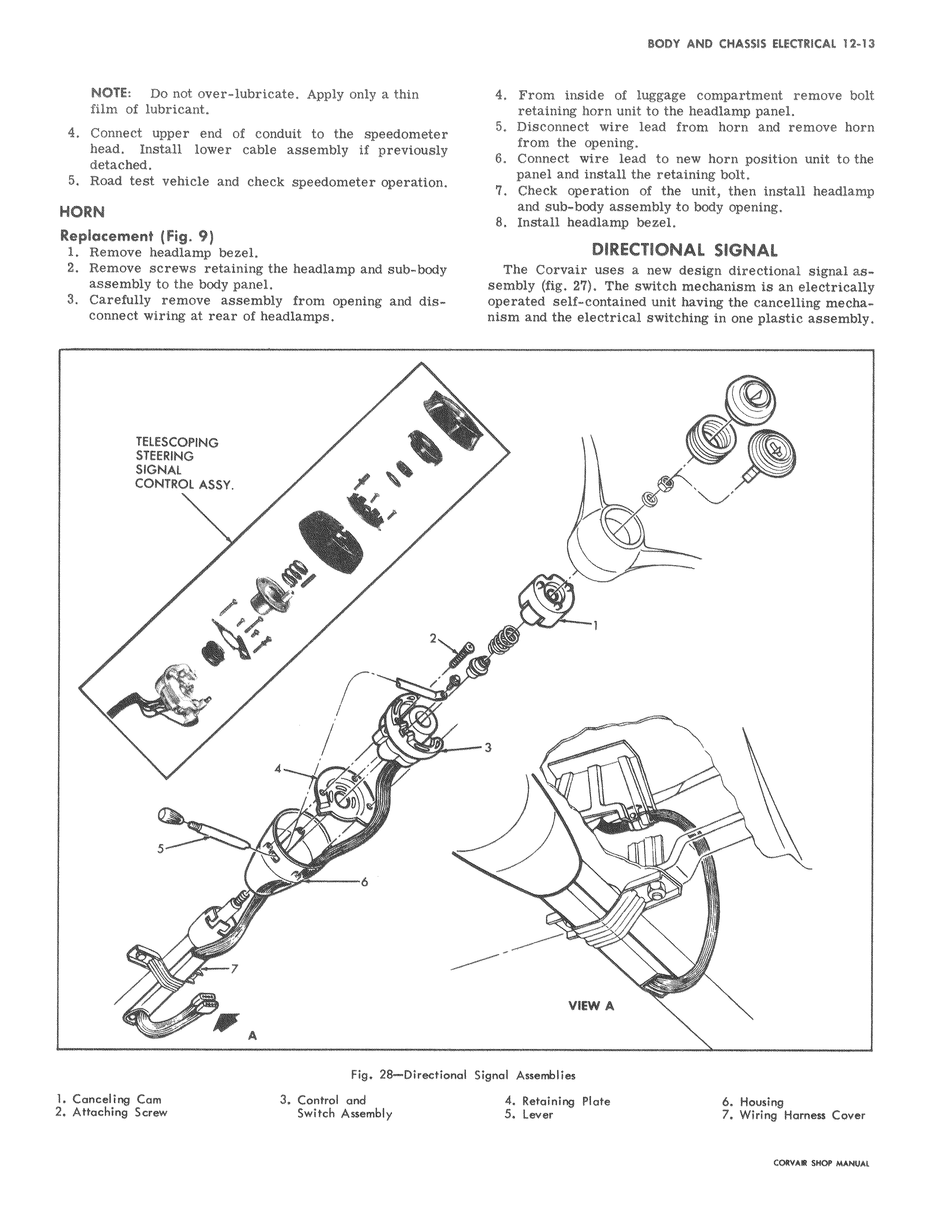
NOTE Do not over lubricate Apply only a thin film of lubricant 4 Connect upper end of conduit to the speedometer head Install lower cable assembly if previously detached 5 Road test vehicle and check speedometer operation HORN Replacement Fig 9 1 Remove headlamp bezel 2 Remove screws retaining the headlamp and sub body assembly to the body panel 3 Carefully remove assembly from opening and disconnect wiring at rear of headlamps TELESCOPING STEERING SIGNAL CONTROL ASSY r i f 4 o 6 7 dam A Fig 28 Di rectior l Canceling Cam 3 Control and 2 Attaching Screw Switch Assembly 4 From inside of luggage compartment remove bolt retaining horn unit to the headlamp panel 5 Disconnect wire lead from horn and remove horn from the opening 6 Connect wire lead to new horn position unit to the panel and install the retaining bolt 7 Check operation of the unit then install headlamp and sub body assembly to body opening 8 Install headlamp bezel DIRECTIONAL SIGNAL The Corvair uses a new design directional signal assembly fig 27 The switch mechanism is an electrically operated self contained unit having the cancelling mechanism and the electrical switching in one plastic assembly v 1 ell 3 v VIEW A al Signal Assemblies 4 Retaining Plate 6 Housing 5 Lever 7 Wiring Harness Cover MlvrR swn u u