Jeep Parts Wiki | Ford Parts Wiki
Home | Search | Browse | Marketplace | Messages | FAQ | Guest
|
Corvair Chassis Shop Manual December 1964 |
|
Prev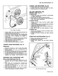
 Next
Next
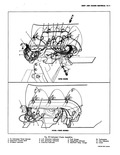
INSTRYMEN S Page General Description 12 1 Service Operations 12 1 Instrument Cluster 12 1 Removal 12 1 Installation 12 1 GENERAL DI All Corvair instrument gauges or indicators cated in the console mounted instrument cluster fig 23 i The entire cluster must be removed to permit servicing of the various instruments and gauges The cluster illuminating and indicator bulbs may be replaced without removing the cluster from the console However it is necessary to remove the heater contro assembly or if so equipped the air conditioning contro assembly The indicator or cluster illuminating lamp sockets may then be snapped in or out of position Regular maintenance is not required on the instrument cluster or its components other than maintaining clean tight electrical connections replacing defective parts and keeping the speedometer cable properly lubricated SERVICE OF INSTRUMENT CLUSTER REMOVAL Fig 23 1 Disconnect battery ground cable 2 Remove steering wheel and mast jacket assembly Refer to Steering Section 9 3 Remove light and wiper switch bezel nuts using Tool J 21932 NOTE On Powerglide models remove shift lever knob 4 Remove heater or air conditioning control retaining screws and allow control to hang below instrument console 5 Disconnect speedometer cable at rear of speedometer housing If so equipped disconnect trip odometer 6 Remove screws retaining instrument cluster assem I bly to console fig 24 Pull instrument cluster assembly forward from console and disconnect cluster wiring harness from panel wiring harness at multiple disconnect fig 23 NOTE On Powerglide models remove shift lever mechanism from rear of cluster housing 8 Remove cluster from the console completely and transfer to a suitable bench area for repair operations INSTALLATION 1 Position instrument cluster assembly to console NOTE On Powerglide models attach shift lever mechanism to cluster assembly I AND GAUGES Page Tachometer 12 10 Temperlature Gauge 12 10 Sendiagi Units 12 10 Speedometer 12 12 Horn Replacement 12 13 SCRIP TION The instrument cluster used with the high performance engines has in addition to the standard Corvair engine warning lights a cylinder head temperature gauge and an engine overheat warning buzzer The gauge indicates cylinder head temperature any time the ignition switch is ON Should the engine overheat the TEMP PRE3S light and the buzzer will operate NOTE If oil pressure is low only the TEMP PRE33 light aprates If the engine temperature is too high both the light and the buzier operate THIS 13 THE POSITIVE WARNING SYSTEM i ERATIiONS 2 Connect cluster wiring harness to instrument panel wiring harness fig 23 3 Install screws retaining cluster assembly to console 4 Connect speedometer cable to rear of speedometer housing connect trip odometer if so equipped 5 Position heater control to cluster and install retaining screws 6 Install light and wiper switch bezel retaining nuts On powerglide models also install shift lever knob 7 Install mast jacket and steering wheel assemblies 8 Connect battery ground cable kid check operation of cluster assembly TACHOMETER The tachometer is a self contained all transistor unit requiring no external relays or batteries and very little service other than keeping the terminal nuts clean and tight TEMPERATURE GAUGE The manifold temperature gauge requires very little servicing other than testing for malfunctioning keeping the connections clean and tight and replacing defective units OIL PRESSURE SENDING UNIT Replacenwnt 1 Disconnect wire lead at switch terminal located at top of oil filter bracket 2 Remove sending switch using Tool J 21757 fig 25 3 Install new switch and reconnect wire lead to terminal