Jeep Parts Wiki | Ford Parts Wiki
Home | Search | Browse
|
Corvair Chassis Shop Manual December 1964 |
|
Prev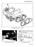
 Next
Next
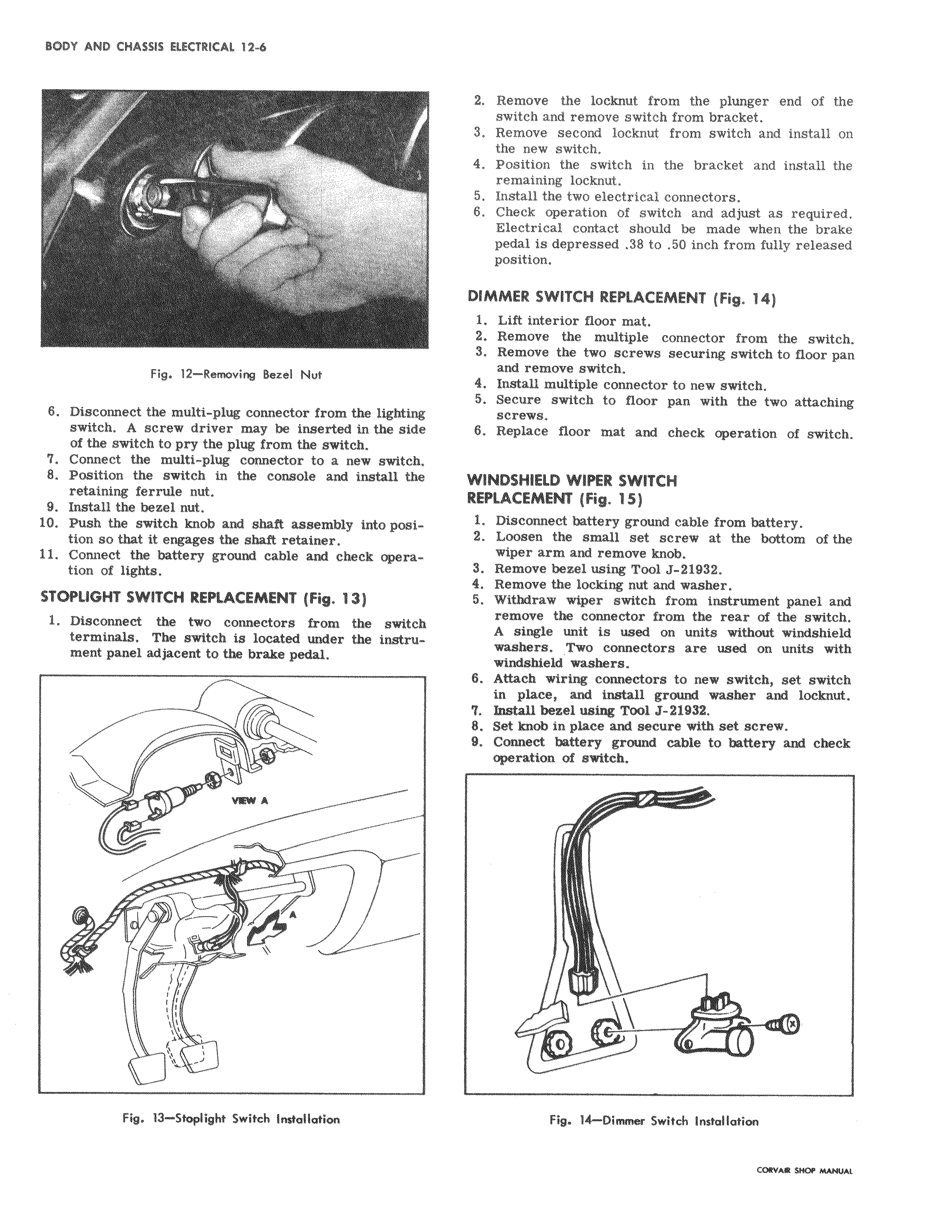
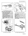
Yn Fig 12 Removing Bezel Nut 6 Disconnect the multi plug connector from the lighting switch A screw driver may be inserted in the side of the switch to pry the plug from the switch 7 Connect the multi plug connector to a new switch 8 Position the switch in the console and install the retaining ferrule nut 9 Install the bezel nut 10 Push the switch knob and shaft assembly into position so that it engages the shaft retainer 11 Connect the battery ground cable and check operation of lights STOPLIGHT SWITCH REPLACEMENT Fig 13 1 Disconnect the two connectors from the switch terminals The switch is located under the instrument panel adjacent to the brake pedal 1 VW a V y y vs I ra Fig 13 Stoplight Switch Installation 2 Remove the locknut from the plunger end of the switch and remove switch from bracket 3 Remove second locknut from switch and install on the new switch 4 Position the switch in the bracket and install the remaining locknut 5 Instill the two electrical connectors 8 Check operation of switch and adjust as required Electrical contact should be made when the brake pedal is depressed 38 to 50 inch from fully released position DIMMER SWITCH REPLACEMENT Fig 14 1 Lift interior floor mat 2 Remove the multiple connector from the switch 3 Remove the two screws securing switch to floor pan and remove switch 4 Install multiple connector to new switch 5 Secure switch to floor pan with the two attaching screws 6 Replace floor mat and check operation of switch WINDSHIELD WIPER SWITCH REPLACEMENT Fig 15 1 Disconnect battery ground cable from battery 2 l oohen the small set screw at the bottom of the wiper arm and remove knob 3 R enlove bezel using Tool J 21932 4 Remove the locking nut and washer 5 Withdraw wiper switch from instrument panel and remove the connector from the rear of the switch A single unit is used on units without windshield washers Two connectors are used on units with windshield washers 6 Attach wiring connectors to new switch set switch in place and install ground washer and loclmut 7 bsWll bezel using Tool J 81932 8 Set knob in place and secure with set screw 9 Con4ect battery ground cable to battery and check operation 02 switch x Fig 14 Dimnw Switch Installation