Jeep Parts Wiki | Ford Parts Wiki
Home | Search | Browse
|
Corvair Chassis Shop Manual December 1964 |
|
Prev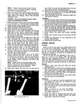
 Next
Next
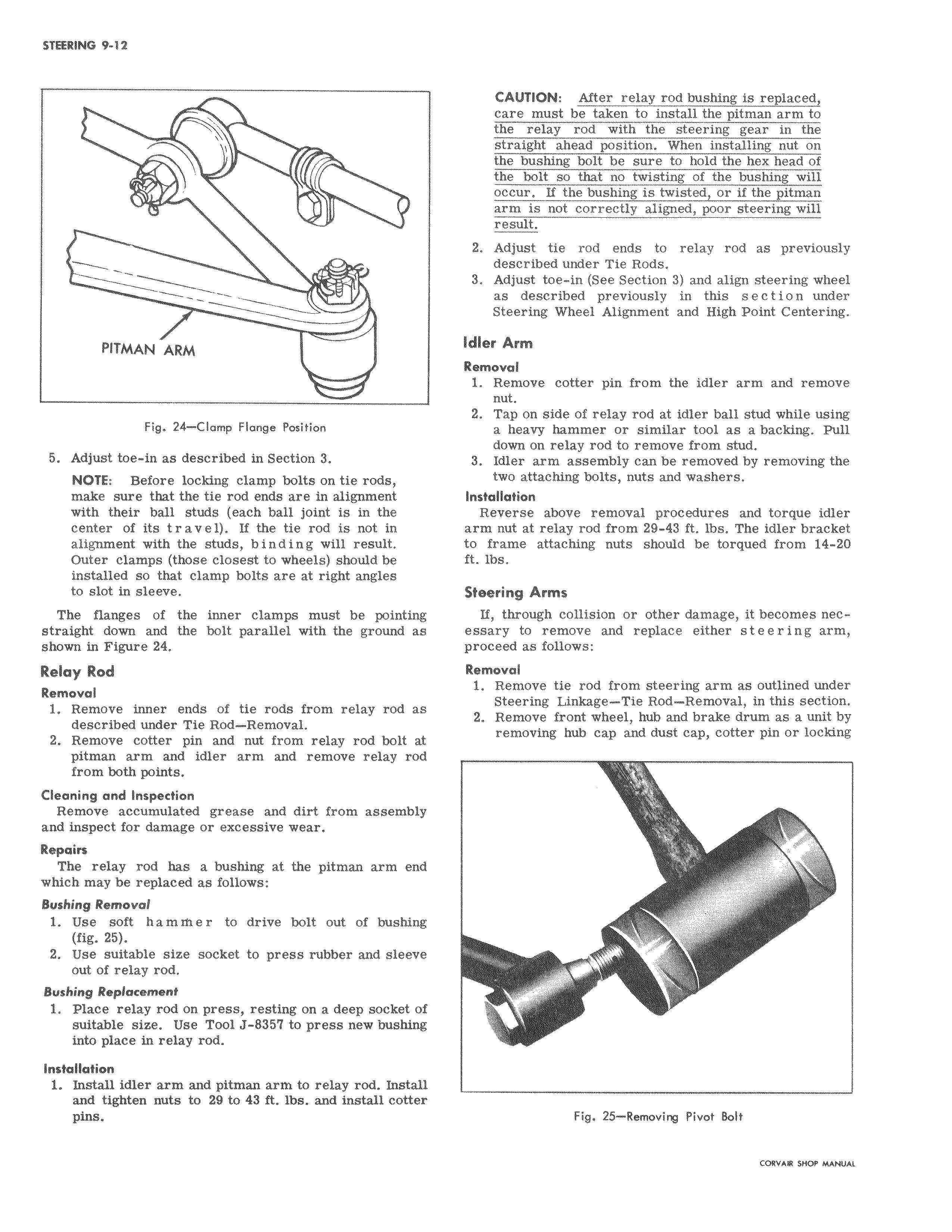
1 J PITMAN ARM Fig 24 Clamp Flange Position 5 Adjust toe in as described in Section 3 NOTE Before locking clamp bolts on tie rods make sure that the tie rod ends are in alignment with their ball studs each ball joint is in the center of its t r a v e 1 If the tie rod is not in alignment with the studs b i n d i n g will result Outer clamps those closest to wheels should be installed so that clamp bolts are at right angles to slot in sleeve The flanges of the inner clamps must be point straight down and the bolt parallel with the ground a s shown in Figure 24 Relay Rod Removal 1 Remove inner ends of tie rods from relay rod s described under Tie Rod Removal 2 Remove cotter pin and nut from relay rod bolt t pitman arm and idler arm and remove relay rod from both points Cleaning and Inspection Remove accumulated grease and dirt from assembly and inspect for damage or excessive wear Repairs The relay rod has a bushing at the pitman arm end which may be replaced as follows Bushing Removal 1 Use soft hammer to drive bolt out of bushing fig 25 2 Use suitable size socket to press rubber and sleeve out of relay rod Bushing Replacement 1 Place relay rod on press resting on a deep socket f suitable size Use Tool J 8357 to press new bushing into place in relay rod Installation 1 Install idler arm and pitman arm to relay rod Inst ll and tighten nuts to 29 to 43 ft lbs and install cotter pins CAUTION After relay rod bushing is replaced care must be taken to install the pitman arm to the relay rod with the steering gear in the ahead position straight the bushing bolt be sure to hold the hex head of lt so that no twisting of the bushing will occur If the bushing is twisted or if the pitman aligned r steering will 2 Adjust tie rod ends to relay rod as previously described under Tie Rods 3 Adjust toe in See Section 3 and align steering wheel described previously under High Point Centering Remove cotter pin from the idler arm and remove Idler Atm Removal while using a heavy hammer r similar tool as a backing Pull down on relay rod to remove from stud 3 Idler arm assembly can be removed by removing the two attaching bolts Installation Reverse above removal procedures and torque idler arm nut at relay rod from 29 43 ft lbs The idler bracket should be torqued from 14 20 collision ft lbs Steering Arms becomes essary to remove and replace either steering arm proceed as follows 1 Remove tie rod from steering arm as outlined under Linkage Tie Rod Removal this Removal Steering 2 Remove front wheel hub and brake drum as a unit by reiioving hub cap and dust cap cotter pin or locking Fig 25 Removirg Pivot Bolt