Jeep Parts Wiki | Ford Parts Wiki
Home | Search | Browse
|
Corvair Chassis Shop Manual December 1964 |
|
Prev
 Next
Next
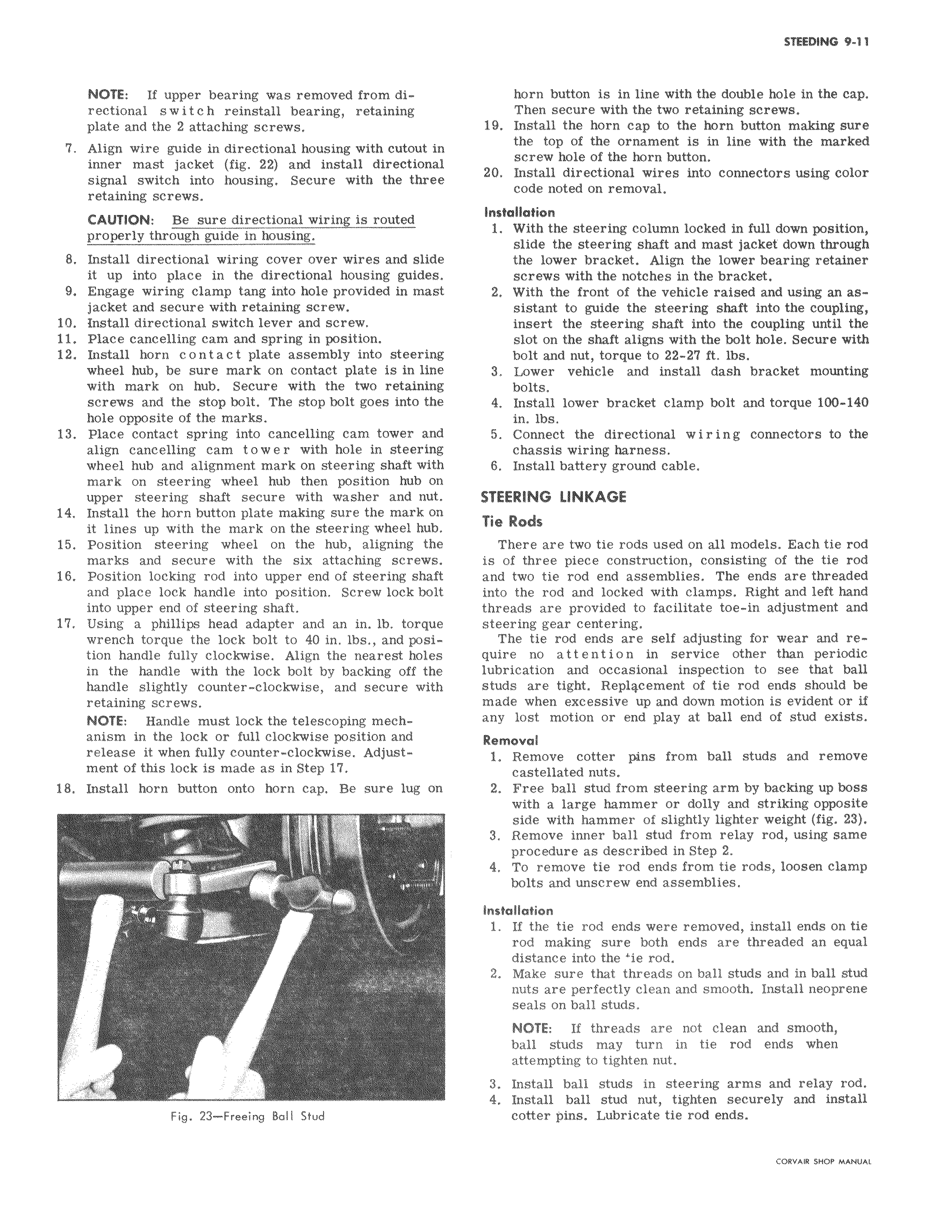
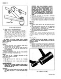
NOTE If upper bearing was removed from directional switch reinstall bearing retaining plate and the 2 attaching screws 7 Align wire guide in directional housing with cutout in inner mast jacket fig 22 and install directional signal switch into housing Secure with the three retaining screws CAUTION Be sure directional wiring is routed properly through guide in housing 8 Install directional wiring cover over wires and slide it up into place in the directional housing guides 9 Engage wiring clamp tang into hole provided in mast jacket and secure with retaining screw 10 Install directional switch lever and screw 11 Place cancelling cam and spring in position 12 Install horn contact plate assembly into steering wheel hub be sure mark on contact plate is in line with mark on hub Secure with the two retaining screws and the stop bolt The stop bolt goes into the hole opposite of the marks 13 Place contact spring into cancelling cam tower and align cancelling cam t o w e r with hole in steering wheel hub and alignment mark on steering shaft with mark on steering wheel hub then position hub on upper steering shaft secure with washer and nut 14 Install the horn button plate making sure the mark on it lines up with the mark on the steering wheel hub 15 Position steering wheel on the hub aligning the marks and secure with the six attaching screws 16 Position locking rod into upper end of steering shaft and place lock handle into position Screw lock bolt into upper end of steering shaft 17 Using a phillips head adapter and an in lb torque wrench torque the lock bolt to 40 in lbs and position handle fully clockwise Align the nearest holes in the handle with the lock bolt by backing off the handle slightly counter clockwise and secure with retaining screws NOTE Handle must lock the telescoping mechanism in the lock or full clockwise position and release it when fully counter clockwise Adjustment of this lock is made as in Step 17 18 Install horn button onto horn cap Be sure lug on f Fig 23 Freeing Ball Stud horn button is in line with the double hole in the cap Then secure with the two retaining screws 19 Install the horn cap to the horn button making sure the top of the ornament is in line with the marked screw hole of the horn button 20 Install directional wires into connectors using color code noted on removal Installation 1 With the steering column locked in full down position slide the steering shaft and mast jacket down through the lower bracket Align the lower bearing retainer screws with the notches in the bracket 2 With the front of the vehicle raised and using an assistant to guide the steering shaft into the coupling insert the steering shaft into the coupling until the slot on the shaft aligns with the bolt hole Secure with bolt and nut torque to 22 27 ft lbs 3 Lower vehicle and install dash bracket mounting bolts 4 Install lower bracket clamp bolt and torque 100 140 in ibs 5 Connect the directional wiring connectors to the chassis wiring harness 6 Install battery ground cable STEERING LINKAGE Tie Rods There are two tie rods used on all models Each tie rod is of three piece construction consisting of the tie rod and two tie rod end assemblies The ends are threaded into the rod and locked with clamps Right and left hand threads are provided to facilitate toe in adjustment and steering gear centering The tie rod ends are self adjusting for wear and require no attention in service other than periodic lubrication and occasional inspection to see that ball studs are tight Repl4cement of tie rod ends should be made when excessive up and down motion is evident or if any lost motion or end play at ball end of stud exists Removal 1 Remove cotter pins from ball studs and remove castellated nuts 2 Free ball stud from steering arm by backing up boss with a large hammer or dolly and striking opposite side with hammer of slightly lighter weight fig 23 3 Remove inner ball stud from relay rod using same procedure as described in Step 2 4 To remove tie rod ends from tie rods loosen clamp bolts and unscrew end assemblies Installation 1 If the tie rod ends were removed install ends on tie rod making sure both ends are threaded an equal distance into the ie rod 2 Make sure that threads on ball studs and in ball stud nuts are perfectly clean and smooth Install neoprene seals on ball studs NOTE If threads are not clean and smooth ball studs may turn in tie rod ends when attempting to tighten nut 3 Install ball studs in steering arms and relay rod 4 Install ball stud nut tighten securely and install cotter pins Lubricate tie rod ends CORVAN SHOP MANUAL