Jeep Parts Wiki | Ford Parts Wiki
Home | Search | Browse
|
Corvair Chassis Shop Manual December 1964 |
|
Prev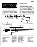
 Next
Next
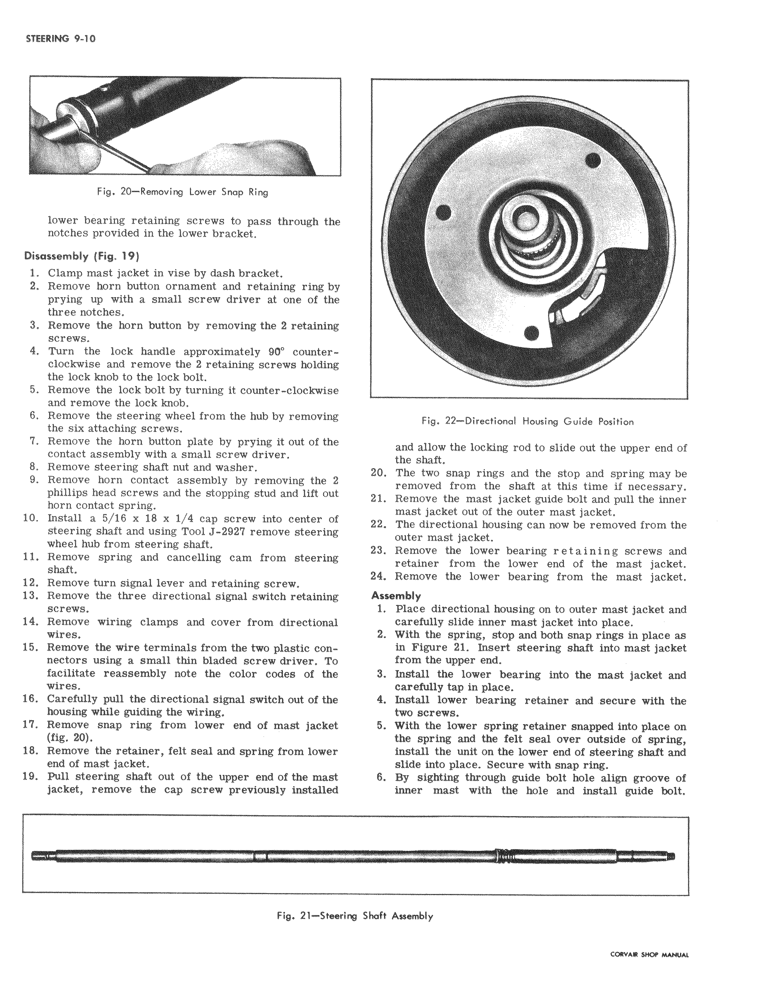
i Fig 20 Removing Lower Snap Ring lower bearing retaining screws to pass through the l notches provided in the lower bracket Disassembly Fig 19 1 Clamp mast jacket in vise by dash bracket i 2 Remove horn button ornament and retaining ring by I prying up with a small screw driver at one of the three notches 3 Remove the horn button by removing the 2 retaining screws 4 Turn the lock handle approximately 90 counter clockwise and remove the 2 retaining screws holding the lock knob to the lock bolt 5 Remove the lock bolt by turning it counter clockwise and remove the lock knob 6 Remove the steering wheel from the hub by removing I the six attaching screws 7 Remove the horn button plate by prying it out of the contact assembly with a small screw driver 8 Remove steering shaft nut and washer 9 Remove horn contact assembly by removing the 2I phillips head screws and the stopping stud and lift out horn contact spring 10 Install a 5 16 x 18 x 1 4 cap screw into center of steering shaft and using Tool J 2927 remove steering wheel hub from steering shaft 11 Remove spring and cancelling cam from steering I shaft 12 Remove turn signal lever and retaining screw 13 Remove the three directional signal switch retaining screws 14 Remove wiring clamps and cover from directional wires 15 Remove the wire terminals from the two plastic con nectors using a small thin bladed screw driver To facilitate reassembly note the color codes of the I wires 16 Carefully pull the directional signal switch out of the housing while guiding the wiring 17 Remove snap ring from lower end of mast jacket l fig 20 18 Remove the retainer felt seal and spring from lower end of mast jacket 19 Pull steering shaft out of the upper end of the mast jacket remove the cap screw previously installed Fig 21 5 ing SF I Fig 22 Directional Housing Guide Position and allow the locking rod to slide out the upper end of the shaft 20 The two snap rings and the stop and spring may be removed from the shaft at this time if necessary tl Remove the mast jacket guide bolt and pull the inner mast jacket out of the outer mast jacket 22 The directional housing can now be removed from the outer mast jacket t3 Remove the lower bearing retaining screws and retainer from the lower end of the mast jacket 14 Remove the lower bearing from the mast jacket Assembly 1 Place directional housing on to outer mast jacket and care ully slide inner mast jacket into place 2 With the spring stop and both snap rings in place as in Figure 21 Insert steering shaft into mast jacket from the upper end 3 Install the lower bearing into the mast jacket and careXully tap in place 4 Install lower bearing retainer and secure with the two screws 5 With the lower spring retainer snapped into place on the spring and the felt seal over outside of spring install the unit on the lower end of steering shaft and slide into place Secure with snap ring 6 By sighting through guide bolt hole align groove of inner mast with the hole and install guide bolt aft Assernbly