Jeep Parts Wiki | Ford Parts Wiki
Home | Search | Browse
|
Corvair Chassis Shop Manual December 1964 |
|
Prev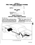
 Next
Next
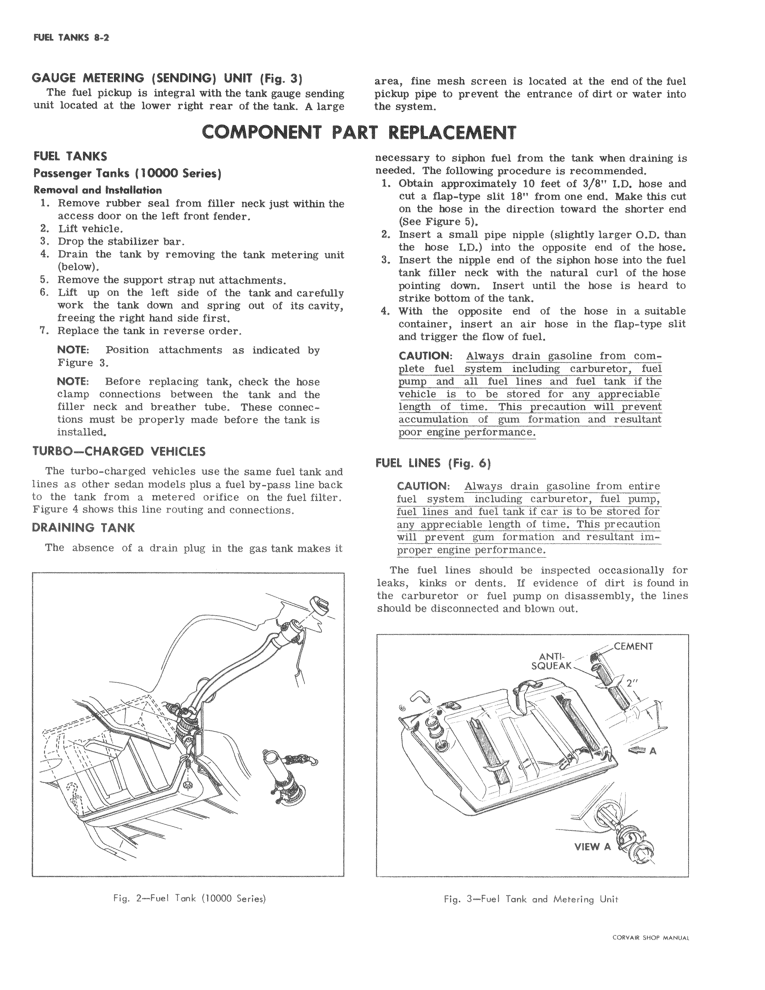
GAUGE METERING SENDING UNIT Fig 3 The fuel pickup is integral with the tank gauge sendink unit located at the lower right rear of the tank A large COMPONENT OAS FUEL TANKS Passenger Tanks 10000 Series Removal and Installation 1 Remove rubber seal from filler neck just within the access door on the left front fender i 2 Lift vehicle 3 Drop the stabilizer bar 4 Drain the tank by removing the tank metering unit below 5 Remove the support strap nut attachments 6 Lift up on the left side of the tank and carefully work the tank down and spring out of its cavity freeing the right hand side first 7 Replace the tank in reverse order NOTE Position attachments as indicated by Figure 3 NOTE Before replacing tank check the hose j clamp connections between the tank and the filler neck and breather tube These connections must be properly made before the tank is installed TURBO CHARGED VEHICLES The turbo charged vehicles use the same fuel tank and lines as other sedan models plus a fuel by pass line back to the tank from a metered orifice on the fuel filte Figure 4 shows this line routing and connections DRAINING TANK The absence of a drain plug in the gas tank makes t S v v v Fig 2 Fuel Tank 10000 Series area fine mesh screen is located at the end of the fuel pickup pipe to prevent the entrance of dirt or water into the sysl m I REPLACEMENT necessary to siphon fuel from the tank when draining is needed The following procedure is recommended 1 Obtain approximately 10 feet of 3 8 LD hose and cut a flap type slit 18 from one end Make this cut on the hose in the direction toward the shorter end So e Figure 6 2 Insert a small pipe nipple slightly larger O D than the hose LD into the opposite end of the hose 3 Insert the nipple end of the siphon hose into the fuel tank filler neck with the natural curl of the hose pointing down Insert until the hose is heard to strike bottom of the tank 4 With the opposite end of the hose in a suitable container insert an air hose in the flap type slit and trigger the flow of fuel CAUTION Always drain gasoline from comQlqte fuel system including carburetor fuel Emp and all fuel lines and fuel tank if the vehicle is to be stored for any appreciable length of time This precaution will prevent ac umulation of gum formation and resultant poor engine performance FUEL LINES Fig 6 CAUTION Always drain gasoline from entire fuel system including carburetor fuel pump fue lines and fuel tank if car is to be stored Forany appreciable length of time This precaution prevent gum formation and resultant improper engine performance The fuel lines should be inspected occasionally for leaks kinks or dents If evidence of dirt is found in the carburetor or fuel pump on disassembly the lines should be disconnected and blown out ANTI CEMENT SQUEAK 2 1 Qft A i r r VIEW A Fig 3 Fuel Tank and Metering Unit