Jeep Parts Wiki | Ford Parts Wiki
Home | Search | Browse
|
Corvair Chassis Shop Manual December 1964 |
|
Prev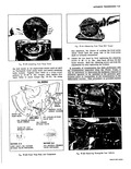
 Next
Next
105194
105194
i in this manual in Section 4 Rear Axle where the instructions for assembly of the Rear Axle to the Power glide are provided POWERGLIDE TRANSMISSION REMOVAL AND INSTALLATION 1 Disconnect engine seal at front shield left and right sides NOTE Disconnect seal from shield by grasping at lower edge and pulling groove of seal off of shield flanges 2 Disconnect starter motor wires at quick disconneGt connector and one battery cable at battery I 3 If so equipped disconnect radio ground straps at left and right shields l 4 Raise vehicle and support on jack stands then remove grille and rear center shield 5 Place engine lift with Tool J 7894 attached unde r engine and support weight of engine 6 Loosen two engine rear mount nuts until nuts are flush with end of stud 7 Disconnect fuel line from body clip so that line can spring away from floor pan 8 Remove two upper retaining bolts from left and right rear strut rod brackets at differential carrier then loosen two lower retaining bolts at left and right rear strut rod bracket approximately 3 turns 9 Disconnect accelerator rods at transmission bellcrank 10 Disconnect left and right front strut rod brackets a engine front mount bracket 11 Disconnect transmission tube and drain transmission 12 Disconnect transmission control cable at transmis sion and disconnect vacuum modulator hose a modulator 13 Disconnect emergency brake return spring front front mount bracket then disconnect emergency brak cable at equalizer 14 Remove cotter keys and remove front mount nuts uiaGN6sP HYDRAULIC PRESSURE DATA I Pressure Top Locations Two pressure tap plugs in the front pump cover are I accessible via holes in the engine front mount front pump pressure is at the 6 o clock position and throttle valve TV pressure is at the 8 o clock position Test Preparation All tests can be made without driving the vehicle byl simply raising the wheels 3 5 inches trom the floor on stand jacks 7Vith pressure gauges installed perform the following preliminary steps Establish pressure gauges indicator needle rest positions at zero pressure Thoroughly warm up transmission Check transmission oil level Check linkage adjustment I 15 Renlove Powerglide governor 16 Lower engine enough for transmission to clear lower body on removal Remove 3 remaining bolts retaining transmission to differential and pull transmission forward far enough to grasp turbine shaft fig 7E 62 then grasping turbine shaft remove transmission with turbine shaft and front pump drive shaft in place NOTE Transmission is removed with engine front bracket attached to transmission 17 For installation of transmission reverse removal procedures NOTE When installing the turbine shaft be careful not to damage its bushings as it is inserted over the front pump drive shaft splines Be sure to engage the two sets of splines When installing transmission to axle align the two units and carefully guide the turbine and front putt4p drive shafts thru the differential carrier so hs not to damage the bushing in the pinion EngAge the splines of the pinion shaft with the planet carrier internal splines Be sure to get full engagement of the splines on the stator shaft turbine shaft and front pump drive shaft with the applicable converter splines by rotating transmission and or slowly turning rear wheels or axle shafts 18 Inst2ill engine seal to shields by lubricating groove of seal with liquid soap or silicone then while guiding groove of seal onto shield flange with one hand press aeai in place with a block of wood or hammer handle 19 Refill transmission with lubricant specified in Section 0 20 Check shift linkage operation and adjust if necessary as outlined under Shift Linkage Adjustment in this Section 21 Check operation of parking brake and accelerator controls adjusting if necessary as outlined in Sections 5 and 6 respectively i GUIDE FRONT PUMP PRESSITRS PSn Range Selector Position Condition R N D L At idle 16 Hg 104 122 52 64 52 64 94 105 At idle with vacuum hose disconnected 184 200 94 105194 105 94 105 at balance tube NOtE Front pump pressures as measured on the front pump pressure gauge are actual pump pressures not mainline pressures and must be obtained with the engine speed at idle i6 Hg