Jeep Parts Wiki | Ford Parts Wiki
Home | Search | Browse | Marketplace | Messages | FAQ | Guest
|
Corvair Chassis Shop Manual December 1964 |
|
Prev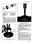
 Next
Next
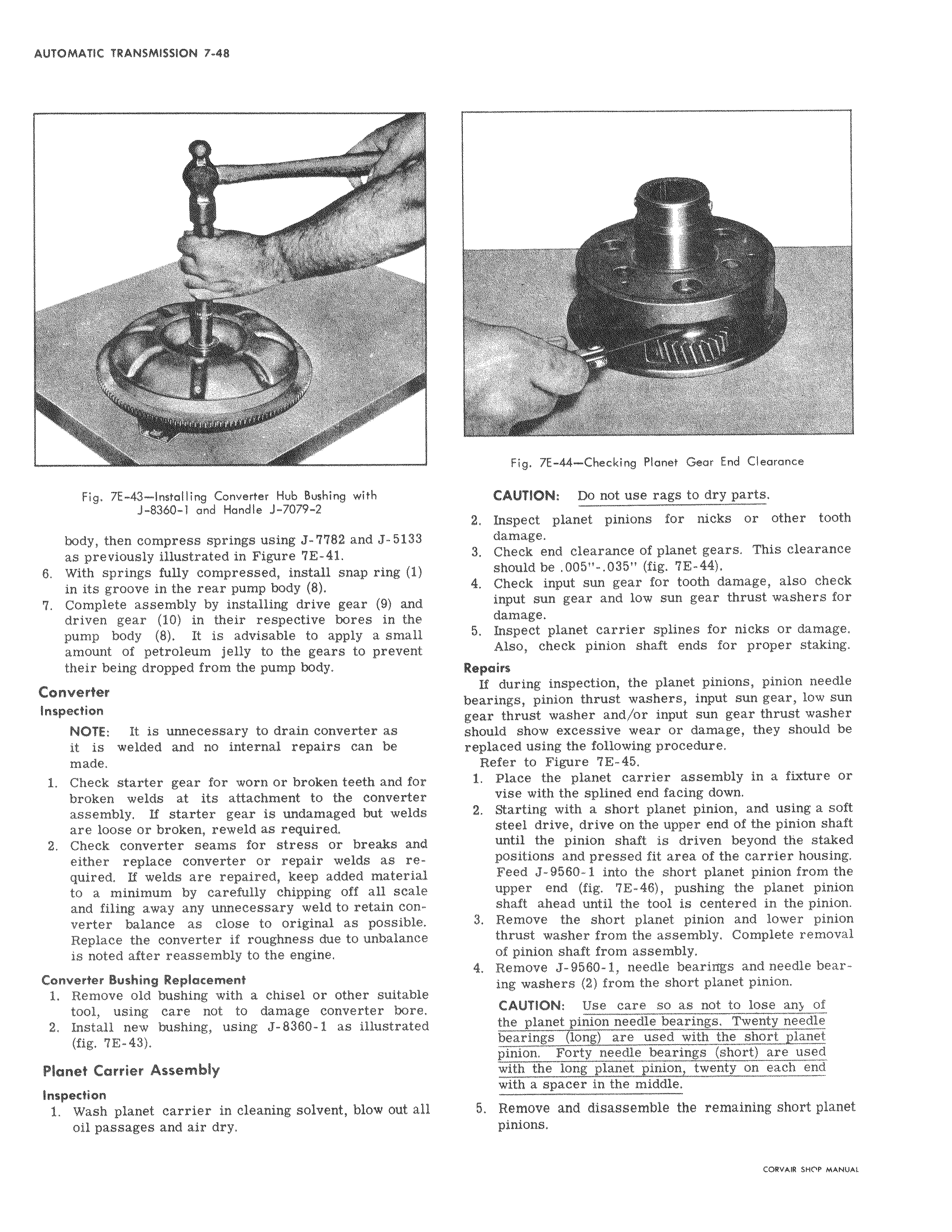
Fig 7E Q Installing Converter Hub Bushing with 1 1 and Handle J 7079 2 body then compress springs using J 7782 and J 513 as previously illustrated in Figure 7E 41 i compressed snap in its groove in the rear pump body 8 7 Complete assembly by installing drive gear 9 and driven gear 10 in their respective bores in the pump body 8 It is advisable to apply a small amount of petroleum jelly to the gears to prevent their being dropped from the pump body NOTE It is unnecessary to drain converter as welded ring 1 Converter Inspection internal o w made e broken d 11 broken welds at its attachment to the converter undamaged i e broken w w b r d rtc w repair welds re quired If welds are repaired keep added material a minimum scale carefully chipping i v e balance e original possible Replace converter roughness due e unbalance is noted after reassembly to the engine 1 Remove old bushing with a chisel or other suitable tool using care not to damage converter bore Install bushing Converter Bushing Replacement 1 w Planet Carrier Assembly Inspection 1 Wash planet carrier in cleaning solvent blow out 11 oil passages and air dry v Pig 7E 44 Checking Planet Gear End Clearance CAUTION Do not use rags to dry parts Inspect planet pinions too 3 Chtck end clearance planet should be 005 035 fig 7E 44 4 Check input sun gear for tooth damage also check input sun gear and low sun gear thrust washers for damage 5 Inspect planet carrier splines for nicks or damage Also check pinion shaft ends for proper staking If during inspection the planet pinions pinion needle bearings pinion thrust washers input sun gear low sun gear thrust washer and or input sun gear thrust washer should i show excessive wear or damage they should be replaced using the following procedure Refer to Figure 7E 45 1 Place the planet carrier assembly in a fixture or vise with the splined end facing down rt planet pinion and using a soft steel drive drive on the upper end of the pinion shaft pinion until the beyond the staked positions and pressed fit area of the carrier housing J 9560 1 into the short planet pinion from the Upper end fig 7E 46 pushing the planet pinion shaft ahead until the tool is centered in the pinion 3 Remove the short planet pinion and lower pinion thrust washer from the assembly Complete removal of pinion shaft from assembly e 1 w b needle ing washers 2 from the short planet pinion e e lw ose the planet pinion needle bearings Twenty needle bearings long are used with the short plane pinion Forty needle bearings short are used a long planet pinion d j spacer r in the middle disassemble i W planet pinions