Jeep Parts Wiki | Ford Parts Wiki
Home | Search | Browse
|
Corvair Chassis Shop Manual December 1964 |
|
Prev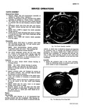
 Next
Next
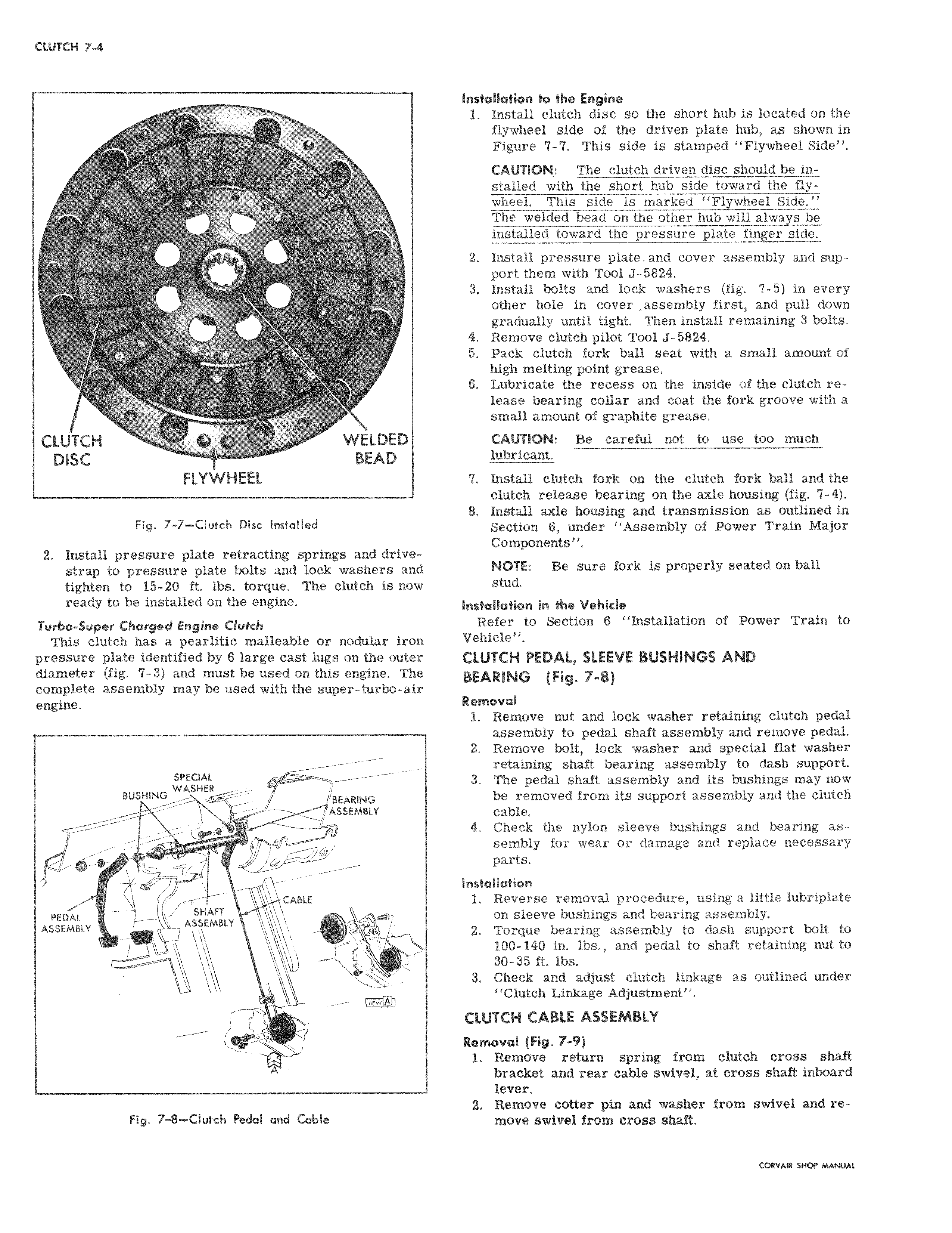
91 I CLUTCH WELDED DISC BEAD FLYWHEEL Fig 7 7 Clutch Disc Installed 2 Install pressure plate retracting springs and drivestrap to pressure plate bolts and lock washers and tighten to 15 20 ft lbs torque The clutch is now ready to be installed on the engine Turbo Super Charged Engine Clutch This clutch has a pearlitic malleable or nodular iron pressure plate identified by 6 large cast lugs on the outer diameter fig 7 3 and must be used on this engine The complete assembly may be used with the super turbo air engine SPECIAL BUSHING WA HER BEARING ASSEMBLY CABLE PEDAL SHAFT ASSEMBLY ASSEMBLY i 1 r Fw r Fig 7 8 Clutch Pedal and Cable Installatidn to the Engine 1 Install clutch disc so the short hub is located on the flywheel side of the driven plate hub as shown in Figure 7 7 This side is stamped Flywheel Side CAUTION The clutch driven disc should be in stalled with the short hub side toward the flywhe This side is marked Flywheel Side The welded bead on the other hub will always be inst led toward the pressure plate finger side 2 Install pressure plate and cover assembly and support them with Tool J 5824 3 Install bolts and lock washers fig 7 5 in every other hole in cover assembly first and pull down gradually until tight Then install remaining 3 bolts 4 Remove clutch pilot Tool J 5824 5 Pack clutch fork ball seat with a small amount of high melting point grease 6 Lubricate the recess on the inside of the clutch release bearing collar and coat the fork groove with a smalt amount of graphite grease CAUTION Be careful not to use too much lubricant 7 Install clutch fork on the clutch fork ball and the clutch release bearing on the axle housing fig 7 4 8 Install axle housing and transmission as outlined in Section 6 under Assembly of Power Train Major Comt onents NOTE Be sure fork is properly seated on ball stud Installation in the Vehicle Refer to Section 6 Installation of Power Train to Vehicle CLUTCH PEDAL SLEEVE BUSHINGS AND BEARING Fig 7 8 Removal 1 Remove nut and lock washer retaining clutch pedal assembly to pedal shaft assembly and remove pedal 2 Remove bolt lock washer and special flat washer retaining shaft bearing assembly to dash support 3 The pedal shaft assembly and its bushings may now be removed from its support assembly and the clutch cable 4 Check the nylon sleeve bushings and bearing assembly for wear or damage and replace necessary parts Installation 1 Reverse removal procedure using a little lubriplate on sleeve bushings and bearing assembly 2 Torque bearing assembly to dash support bolt to 100 140 in lbs and pedal to shaft retaining nut to 30 36 ft lbs 3 Check and adjust clutch linkage as outlined under Clutch Linkage Adjustment CLUTCH CABLE ASSEMBLY Removal Fig 7 9 1 Remove return spring from clutch cross shaft bra ket and rear cable swivel at cross shaft inboard lever 2 ReMove cotter pin and washer from swivel and removi swivel from cross shaft