Jeep Parts Wiki | Ford Parts Wiki
Home | Search | Browse | Marketplace | Messages | FAQ | Guest
|
Corvair Chassis Shop Manual December 1964 |
|
Prev

 Next
Next
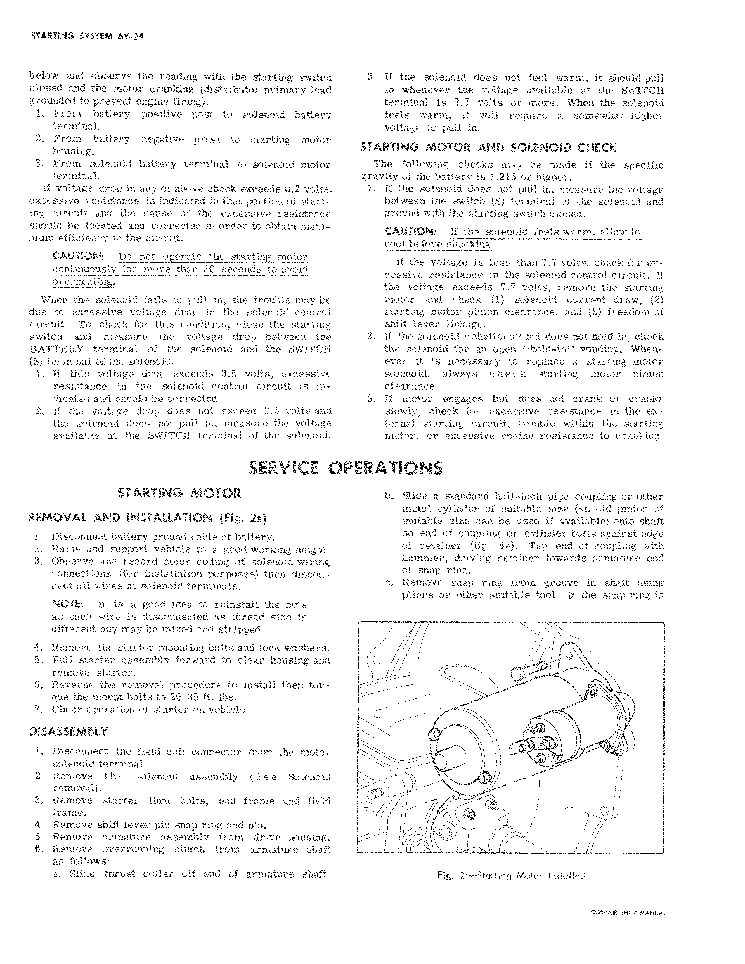
below and observe the reading with the starting switchl closed and the motor cranking distributor primary leadi grounded to prevent engine firing 1 From battery positive post to solenoid battery terminal 2 From battery negative post to starting motor I housing 3 From solenoid battery terminal to solenoid motorl terminal I If voltage drop in any of above check exceeds 0 2 volts excessive resistance is indicated in that portion of start ing circuit and the cause of the excessive resistance should be located and corrected in order to obtain maxi I mum efficiency in the circuit CAUTION Do not operate the starting motor continuously for more than 30 seconds to avoid overheating When the solenoid fails to pull in the trouble may be due to excessive voltage drop in the solenoid control circuit To check for this condition close the starting switch and measure the voltage drop between the BATTERY terminal of the solenoid and the SWITCH S terminal of the solenoid 1 If this voltage drop exceeds 3 5 volts excessive resistance in the solenoid control circuit is indicated and should be corrected I 2 If the voltage drop does not exceed 3 5 volts and the solenoid does not pull in measure the voltage available at the SWITCH terminal of the solenoid SERVICE I pPI STARTING MOTOR REMOVAL AND INSTALLATION Fig 2s 1 Disconnect battery ground cable at battery 2 Raise and support vehicle to a good working heightIl 3 Observe and record color coding of solenoid wirinr connections for installation purposes then discon nect all wires at solenoid terminals NOTE It is a good idea to reinstall the nuts as each wire is disconnected as thread size is different buy may be mixed and stripped 4 Remove the starter mounting bolts and lock washer I 5 Pull starter assembly forward to clear housing it remove starter 6 Reverse the removal procedure to install then torl que the mount bolts to 25 35 ft lbs 7 Check operation of starter on vehicle DISASSEMBLY 1 Disconnect the field coil connector from the motor solenoid terminal 2 Remove the solenoid assembly See Solenoid removal 3 Remove starter thru bolts end frame and field frame 4 Remove shift lever pin snap ring and pin 5 Remove armature assembly from drive housing 6 Remove overrunning clutch from armature shaft as follows a Slide thrust collar off end of armature shaft I 3 If tlie solenoid does not feel warm it should pull in whenever the voltage available at the SWITCH terminal is 7 7 volts or more When the solenoid feels warm it will require a somewhat higher voltage to pull in STARTING MOTOR AND SOLENOID CHECK The following checks may be made if the specific gravity of the battery is 1 215 or higher 1 If the solenoid does not pull in measure the voltage between the switch S terminal of the solenoid and ground with the starting switch closed CAUTION If the solenoid feels warm allow to cool before checking If the voltage is less than 7 7 volts check for excessive resistance in the solenoid control circuit If the voltage exceeds 7 7 volts remove the starting motor and check 1 solenoid current draw 2 starting motor pinion clearance and 3 freedom of shift lever linkage 2 If the solenoid chatters but does not hold in check the solenoid for an open hold in winding Whenever it is necessary to replace a starting motor solenoid always c h e c k starting motor pinion clealrance 3 If iotor engages but does not crank or cranks slowly check for excessive resistance in the external starting circuit trouble within the starting motor or excessive engine resistance to cranking ERATIQNS b Slide a standard half inch pipe coupling or other metal cylinder of suitable size an old pinion of suitable size can be used if available onto shaft so end of coupling or cylinder butts against edge of retainer fig 4s Tap end of coupling with hammer driving retainer towards armature end of snap ring c Remove snap ring from groove in shaft using pliers or other suitable tool If the snap ring is i i 0 i i Fig 2s Starting Motor Installed

 Next
Next