Jeep Parts Wiki | Ford Parts Wiki
Home | Search | Browse
|
Corvair Chassis Shop Manual December 1964 |
|
Prev

 Next
Next
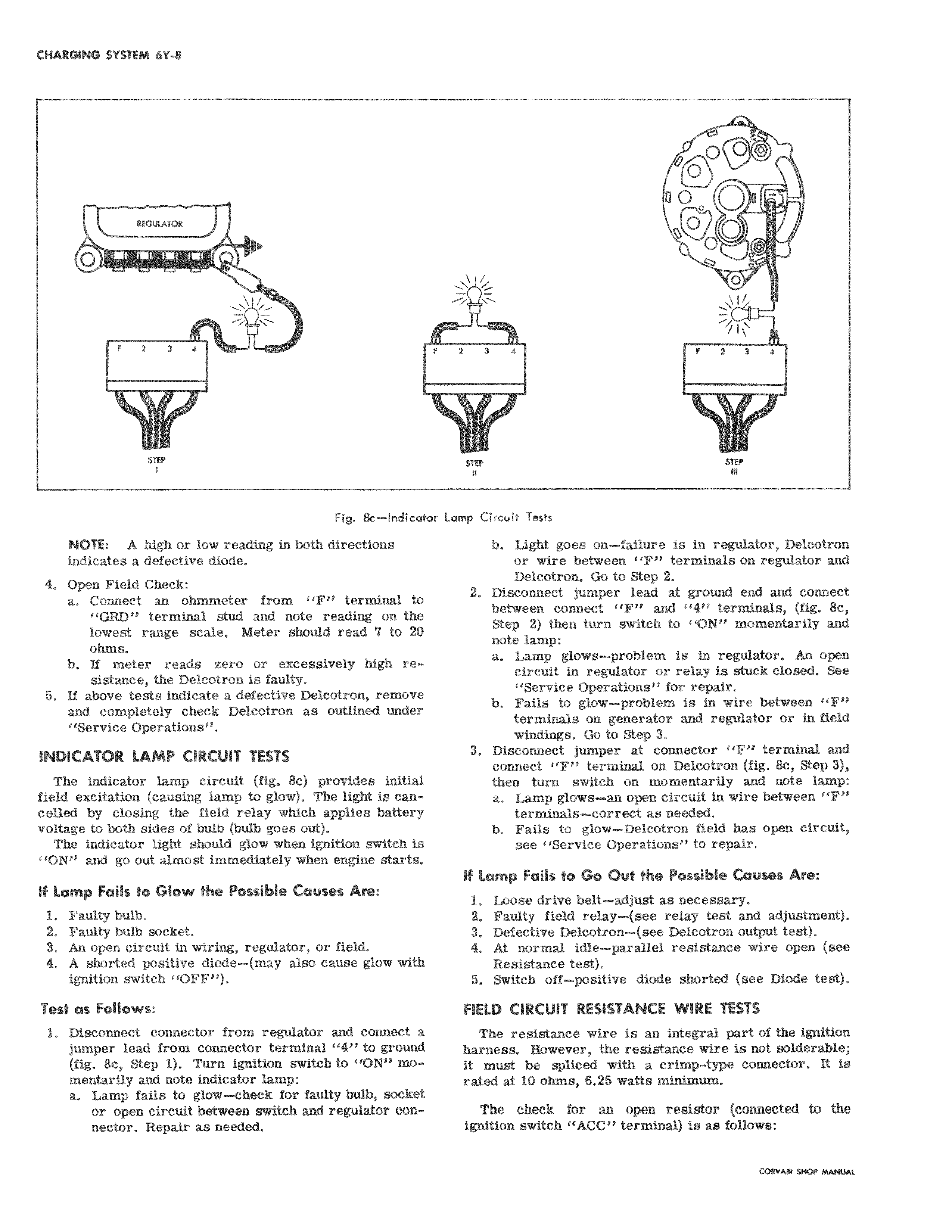
KG41L aR 1 O r f 2 3 1 f STEP I Fig 8c Indicator Lv NOTE A high or low reading in both directions indicates a defective diode 4 Open Field Check a Connect an ohmmeter from F terminal to GRD terminal stud and note reading on the lowest range scale Meter should read 7 to 20 ohms b If meter reads zero or excessively high resistance the Delcotron is faulty 5 If above tests indicate a defective Delcotron remove i and completely check Delcotron as outlined under Service Operations INDICATOR LAMP CIRCUIT TESTS The indicator lamp circuit fig 8c provides initial field excitation causing lamp to glow The light is cancelled by closing the field relay which applies battery voltage to both sides of bulb bulb goes out The indicator light should glow when ignition switch is ON and go out almost immediately when engine starts If Lamp Fails 1o Glow the Possible Causes Are 1 Faulty bulb 2 Faulty bulb socket 3 An open circuit in wiring regulator or field 4 A shorted positive diode may also cause glow with ignition switch OFF Test as Follows 1 Disconnect connector from regulator and connect a jumper lead from connector terminal 11411 to ground fig 8c Step 1 Turn ignition switch to ON mo mentarily and note indicator lamp a Lamp fails to glow check for faulty bulb socket or open circuit between switch and regulator connector Repair as needed T OO 0 W O 2 3 1 f 2 3 1 619 87B imp Circuit Tests b Light goes on failure is in regulator Delcotron or wire between F terminals on regulator and Delcotron Go to Step 2 2 Disconnect jumper lead at ground end and connect between connect F and 4 terminals fig 8c Step 2 then turn switch to ON momentarily and note lamp a Lamp glows problem is in regulator An open circuit in regulator or relay is stuck closed See Service Operations for repair b Fails to glow problem is in wire between F tprminals on generator and regulator or in field windings Go to Step 3 3 Disconnect jumper at connector IF terminal and connect F terminal on Delcotron fig 8c Step 3 then turn switch on momentarily and note lamp a Lamp glows an open circuit in wire between F terminals correct as needed b Fails to glow Delcotron field has open circuit sloe Service Operations to repair If Lamp Fails to Go Out the Possible Causes Are 1 Loose drive belt adjust as necessary 2 Faulty field relay see relay test and adjustment 3 Defective Delcotron see Delcotron output test 4 At normal idle parallel resistance wire open see Reststance test 5 Switch off positive diode shorted see Diode test FIELD CIRCUIT RESISTANCE WIRE TESTS The rosistauce wire is an integral part of the ignition harness However the resistance wire is not solderable it must Ibe spliced with a crimp type connector It is rated at 1 0 ohms 6 25 watts minimum The clheck for an open resistor connected to the ignition switch ACC terminal is as follows

 Next
Next