Jeep Parts Wiki | Ford Parts Wiki
Home | Search | Browse
|
Corvair Chassis Shop Manual December 1964 |
|
Prev
 Next
Next
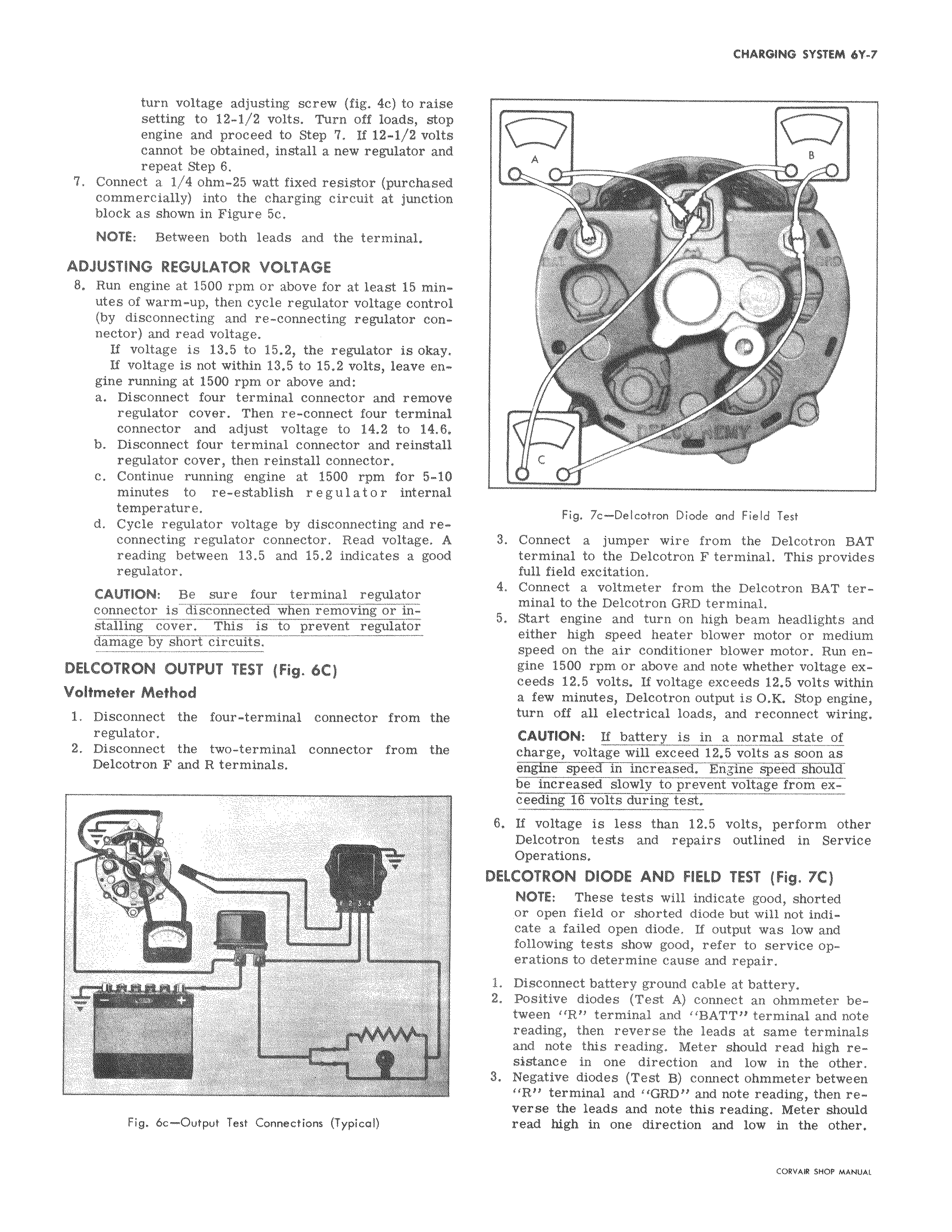
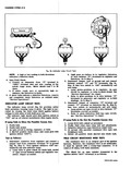
turn voltage adjusting screw fig 4c to raise setting to 12 1 2 volts Turn off loads stop engine and proceed to Step 7 If 12 1 2 volts cannot be obtained install a new regulator and repeat Step 6 7 Connect a i 4 ohm 25 watt fixed resistor purchased commercially into the charging circuit at junction block as shown in Figure 5c NOTE Between both leads and the terminal ADJUSTING REGULATOR VOLTAGE 8 Run engine at 1500 rpm or above for at least 15 minutes of warm up then cycle regulator voltage control by disconnecting and re connecting regulator connector and read voltage If voltage is 13 5 to 15 2 the regulator is okay If voltage is not within 13 5 to 15 2 volts leave engine running at 1500 rpm or above and a Disconnect four terminal connector and remove regulator cover Then re connect four terminal connector and adjust voltage to 14 2 to 14 6 b Disconnect four terminal connector and reinstall regulator cover then reinstall connector c Continue running engine at 1500 rpm for 5 10 minutes to re establish regulator internal temperature d Cycle regulator voltage by disconnecting and reconnecting regulator connector Read voltage A reading between 13 5 and 15 2 indicates a good regulator CAUTION Be sure four terminal regulator connector is disconnected when removing or installing cover This is to prevent regulator damage by short circuits DELCOTRON OUTPUT TEST Fig 6C Voltmeter Method i Disconnect the four terminal connector from the regulator 2 Disconnect the two terminal connector from the Delcotron F and R terminals t i 5 rf u T W Fig 6c Output Test Connections Typical A v l Y r 40 Fig 7c Delcotron Diode and Field Test 3 Connect a jumper wire from the Delcotron BAT terminal to the Delcotron F terminal This provides full field excitation 4 Connect a voltmeter from the Delcotron BAT terminal to the Delcotron GR D terminal 5 Start engine and turn on high beam headlights and either high speed heater blower motor or medium speed on the air conditioner blower motor Run engine 1500 rpm or above and note whether voltage exceeds 12 5 volts If voltage exceeds 12 5 volts within a few minutes Delcotron output is O K Stop engine turn off all electrical loads and reconnect wiring CAUTION If battery is in a normal state of charge voltage will exceed 12 5 volts as soon as engine speed in increased Engine speed should be increased slowly to prevent voltage from exceeding 16 volts during test 6 If voltage is less than 12 5 volts perform other Deicotron tests and repairs outlined in Service Operations DELCOTRON DIODE AND FIELD TEST Fig 7C NOTE These tests will indicate good shorted or open field or shorted diode but will not indi cate a failed open diode If output was low and following tests show good refer to service operations to determine cause and repair 1 Disconnect battery ground cable at battery 2 Positive diodes Test A connect an ohmmeter between R terminal and BATT terminal and note reading then reverse the leads at same terminals and note this reading Meter should read high resistance in one direction and low in the other 3 Negative diodes Test B connect ohmmeter between R terminal and 11GRD and note reading then reverse the leads and note this reading Meter should read high in one direction and low in the other