Jeep Parts Wiki | Ford Parts Wiki
Home | Search | Browse | Marketplace | Messages | FAQ | Guest
|
Corvair Chassis Shop Manual December 1964 |
|
Prev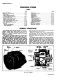
 Next
Next
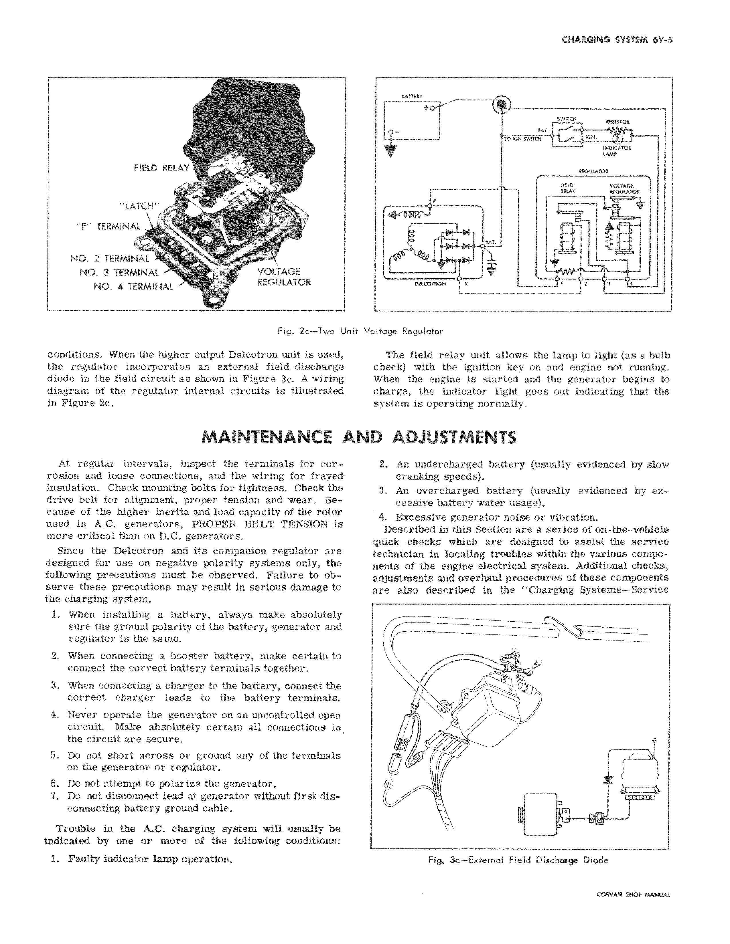
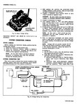
a FIELD RELAY o0 LATCH F TERMINAL NO 2 TERMINAL NO 3 TERMINAL VOLTAGE NO 4 TERMINAL REGULATOR Fig 2e Two Ui conditions When the higher output Delcotron unit is used the regulator incorporates an external field discharge diode in the field circuit as shown in Figure 3a A wiring diagram of the regulator internal circuits is illustrated in Figure 2c MAINTENANCE I At regular intervals inspect the terminals for corrosion and loose connections and the wiring for frayed insulation Check mounting bolts for tightness Check the drive belt for alignment proper tension and wear Because of the higher inertia and load capacity of the rotor used in A C generators PROPER BELT TENSION is more critical than on D C generators Since the Delcotron and its companion regulator are designed for use on negative polarity systems only the following precautions must be observed Failure to observe these precautions may result in serious damage to the charging system 1 When installing a battery always make absolutely sure the ground polarity of the battery generator and regulator is the same 2 When connecting a booster battery make certain to connect the correct battery terminals together 3 When connecting a charger to the battery connect the correct charger leads to the battery terminals 4 Never operate the generator on an uncontrolled open circuit Make absolutely certain all connections in the circuit are secure 5 Do not short across or ground any of the terminals on the generator or regulator 6 Do not attempt to polarize the generator 7 Do not disconnect lead at generator without first disconnecting battery ground cable Trouble in the A C charging system will usually be indicated by one or more of the following conditions 1 Faulty indicator lamp operation BATTERY t SWITCH ur ro arr SWITCH ION acAro LAW iaauAra FOLD VOLTAGE RELAY 00MILATOR f i MT 1 J p DflOOrlON f i 2 7 1 L Ut J vit Voitage Regulator The field relay unit allows the lamp to light as a bulb check with the ignition key on and engine not running When the engine is started and the generator begins to charge the indicator light goes out indicating that the system is operating normally WD ADJUSTMENTS 2 An undercharged battery usually evidenced by slow cranking speeds 3 An overcharged battery usually evidenced by excessive battery water usage 4 Excessive generator noise or vibration Described in this Section are a series of on the vehicle quick checks which are designed to assist the service technician in locating troubles within the various components of the engine electrical system Additional checks adjustments and overhaul procedures of these components are also described in the Charging Systems Service v i e acc Fig 3c Extemol Field Discharge Diode