Jeep Parts Wiki | Ford Parts Wiki
Home | Search | Browse
|
Corvair Chassis Shop Manual December 1964 |
|
Prev

 Next
Next
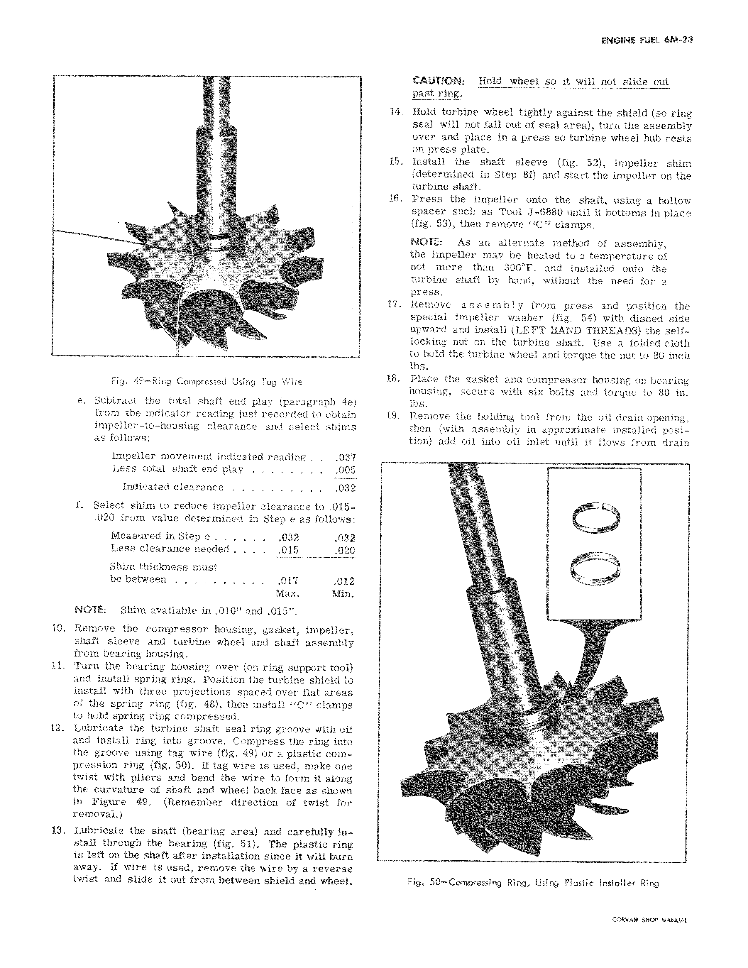
Fig 49 Ring Compressed Using Tag Wire e Subtract the total shaft end play paragraph 4e from the indicator reading just recorded to obtain impeller to housing clearance and select shims as follows Impeller movement indicated reading 037 Less total shaft end play 005 Indicated clearance 03Z f Select shim to reduce impeller clearance to 015 020 from value determined in Step e as follows Measured in Step e 032 032 Less clearance needed 015 020 Shim thickness must be between 017 012 Max Min NOTE Shim available in 010 and 015 10 Remove the compressor housing gasket impeller shaft sleeve and turbine wheel and shaft assembly from bearing housing 11 Turn the bearing housing over on ring support tool and install spring ring Position the turbine shield to install with three projections spaced over flat areas of the spring ring fig 48 then install C clamps to hold spring ring compressed 12 Lubricate the turbine shaft seal ring groove with oi and install ring into groove Compress the ring into the groove using tag wire fig 49 or a plastic com pression ring fig 50 If tag wire is used make one twist with pliers and bend the wire to form it along the curvature of shaft and wheel back face as shown in Figure 49 Remember direction of twist for removal 13 Lubricate the shaft bearing area and carefully install through the bearing fig 51 The plastic ring is left on the shaft after installation since it will burn away If wire is used remove the wire by a reverse twist and slide it out from between shield and wheel CAUTION Hold wheel so it will not slide out past ring 14 Hold turbine wheel tightly against the shield so ring seal will not fall out of seal area turn the assembly over and place in a press so turbine wheel hub rests on press plate 15 Install the shaft sleeve fig 52 impeller shim determined in Step Sf and start the impeller on the turbine shaft 16 Press the impeller onto the shaft using a hollow spacer such as Tool J 6880 until it bottoms in place fig 53 then remove C clamps NOTE As an alternate method of assembly the impeller may be heated to a temperature of not more than 300 F and installed onto the turbine shaft by hand without the need for a press 17 Remove assembly from press and position the special impeller washer fig 54 with dished side upward and install LEFT HAND THREADS the self locking nut on the turbine shaft Use a folded cloth to hold the turbine wheel and torque the nut to 80 inch lbs 18 Place the gasket and compressor housing on bearing housing secure with six bolts and torque to 80 in lbs 19 Remove the holding tool from the oil drain opening then with assembly in approximate installed position add oil into oil inlet until it flows from drain r Fig 50 Compressing Ring Using Plastic Installer Ring

 Next
Next