Jeep Parts Wiki | Ford Parts Wiki
Home | Search | Browse
|
Corvair Chassis Shop Manual December 1964 |
|
Prev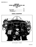
 Next
Next
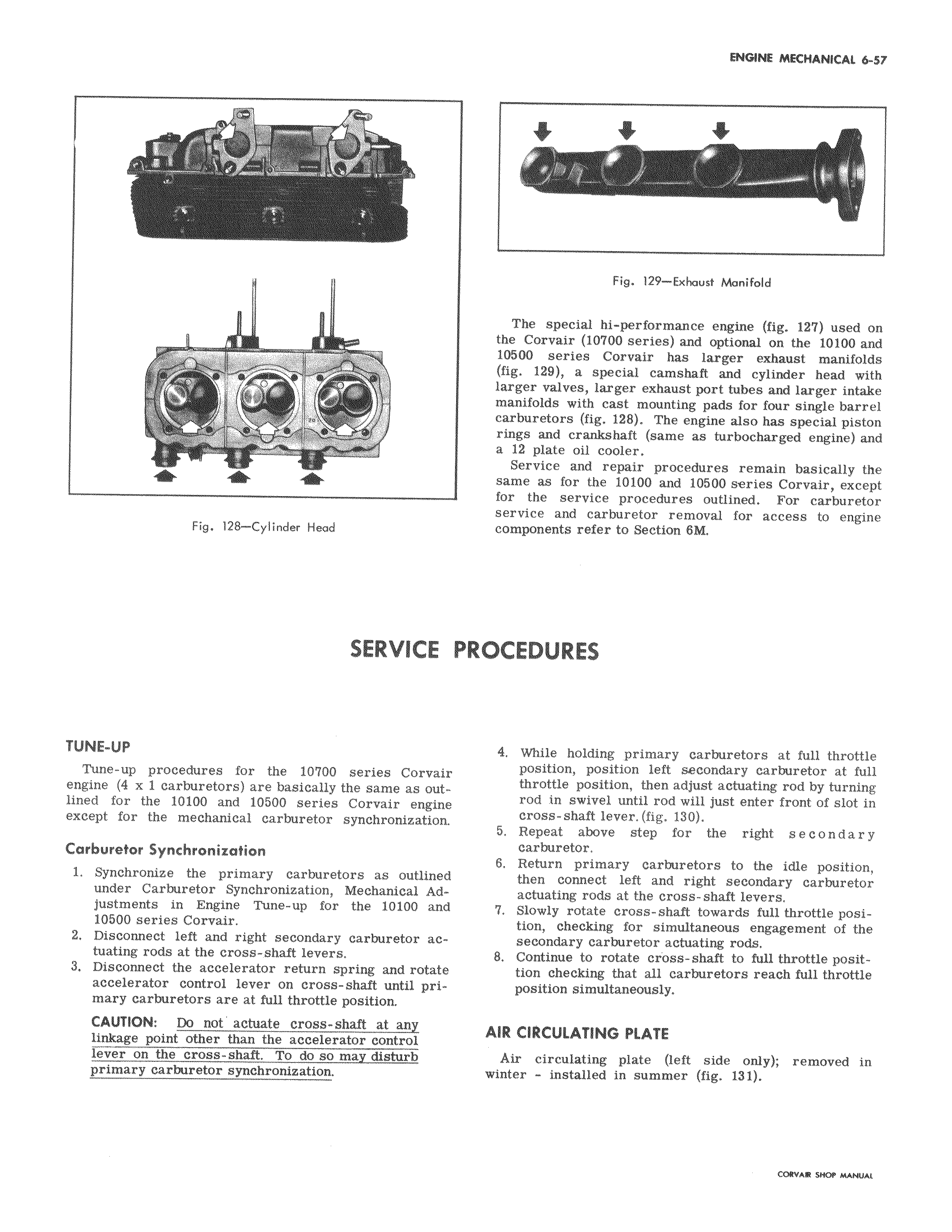
a J fill Fig 128 Cylinder Head SERVICE TUNE UP Tune up procedures for the 10700 series Corvair engine 4 x 1 carburetors are basically the same as outlined for the 10100 and 10500 series Corvair engine except for the mechanical carburetor synchronization Carburetor Synchronization 1 Synchronize the primary carburetors as outlined under Carburetor Synchronization Mechanical Adjustments in Engine Tune up for the 10100 and 10500 series Corvair 2 Disconnect left and right secondary carburetor actuating rods at the cross shaft levers 3 Disconnect the accelerator return spring and rotate accelerator control lever on cross shaft until primary carburetors are at full throttle position CAUTION Do not actuate cross shaft at any linkage point other than the accelerator control lever on the cross shaft To do so may disturb primary carburetor synchronization i i Fig 129 Exhaust Manifold The special hi performance engine fig 12 used on the Corvair 10700 series and optional on the 10100 and 10500 series Corvair has larger exhaust manifolds fig 129 a special camshaft and cylinder head with larger valves larger exhaust port tubes and larger intake manifolds with cast mounting pads for four single barrel carburetors fig 128 The engine also has special piston rings and crankshaft same as turbocharged engine and a 12 plate oil cooler Service and repair procedures remain basically the same as for the 10100 and 10500 series Corvair except for the service procedures outlined For carburetor service and carburetor removal for access to engine components refer to Section 8M PROCEDURES 4 While holding primary carburetors at full throttle position position left secondary carburetor at full throttle position then adjust actuating rod by turning rod in swivel until rod will just enter front of slot in cross shaft lever fig 130 5 Repeat above step for the right s e c o n d a r y carburetor 6 Return primary carburetors to the idle position then connect left and right secondary carburetor actuating rods at the cross shaft levers 7 Slowly rotate cross shaft towards full throttle position checking for simultaneous engagement of the secondary carburetor actuating rods 8 Continue to rotate cioss shaft to full throttle posittion checking that all carburetors reach full throttle position simultaneously AIR CIRCULATING PLATE Air circulating plate left side only removed in winter installed in summer fig 131